Blu link – Crown Audio DCi Series – Network Input Models User Manual
Page 33
DriveCore Install Network Series
Power Amplifiers
page 33
Operation Manual
Any multi-transport combination NOT specifically listed above is not allowed in Soundweb London systems (without being forced to use analog interconnects between
transports). For example, BLU link + AVB + CobraNet is NOT allowed, because the AVB and CobraNet networks would each be synced to different clocks—their own.
Mastership is negotiated between all the devices on the ring, and change to the ring will trigger the negotiation to be started. There are various rules for determining which
device on the ring becomes clock master :
• If there is only one device connected to CobraNet/AVB then that is master.
• If there are multiple devices connected to CobraNet/AVB, then they compare master priorities.
• If there are multiple devices on CobraNet/AVB with the same highest priority, then they use MAC address to decide which is master.
• If there are no devices connected to CobraNet/AVB, then they first compare master priorities. Next, if the priorities are the same, they compare MAC addresses.
BLU Link Routing
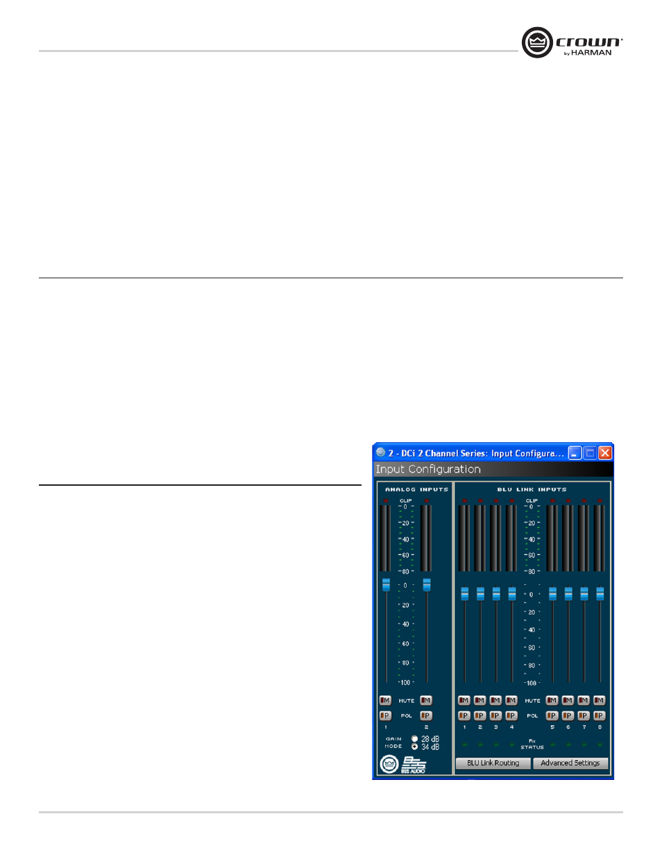
Input Configuration
The DriveCore Install Network Amplifiers series can utilize both analog or BLU Link inputs.
To configured the input section of the amplifier, Input Icon > Source Routing > Input
Configuration. This page allows you to make changes to the levels of the various sources.
This feature allows you to not only adjust for different signal levels from the source
(i.e. analog is quieter than BLU Link ) as well as being able to be used for an additional
location of gain if needed. The meters on this page allow you to see both Peak and RMS
levels. You are also able to set the maximum input level for the amplifier which will affect
both channels. Rx Status lights below each BLU Link input channel provide confirmation
of slot assignment.
NOTE: Gain Mode for the analog inputs can be used to maximize the Signal to Noise Ratio.
BLU Link
Figure 20 Input Configuration
BLU-link LED indicators
These are found on the Blu link ports on the back panel of the device and indicate the following:
• Green LEDs
The green LED will indicate a link on that particular port
• Orange LEDs
Both on: The box is the master. (No green LEDs will be on if no cables are connected).
Only one on: The box is locked to the data coming in on that particular port
Both off: Boxes not locked