Set-up and system configuration – Crown Audio DCi Series – Network Input Models User Manual
Page 21
DriveCore Install Network Series
Power Amplifiers
page 21
Operation Manual
Set-up and System Configuration
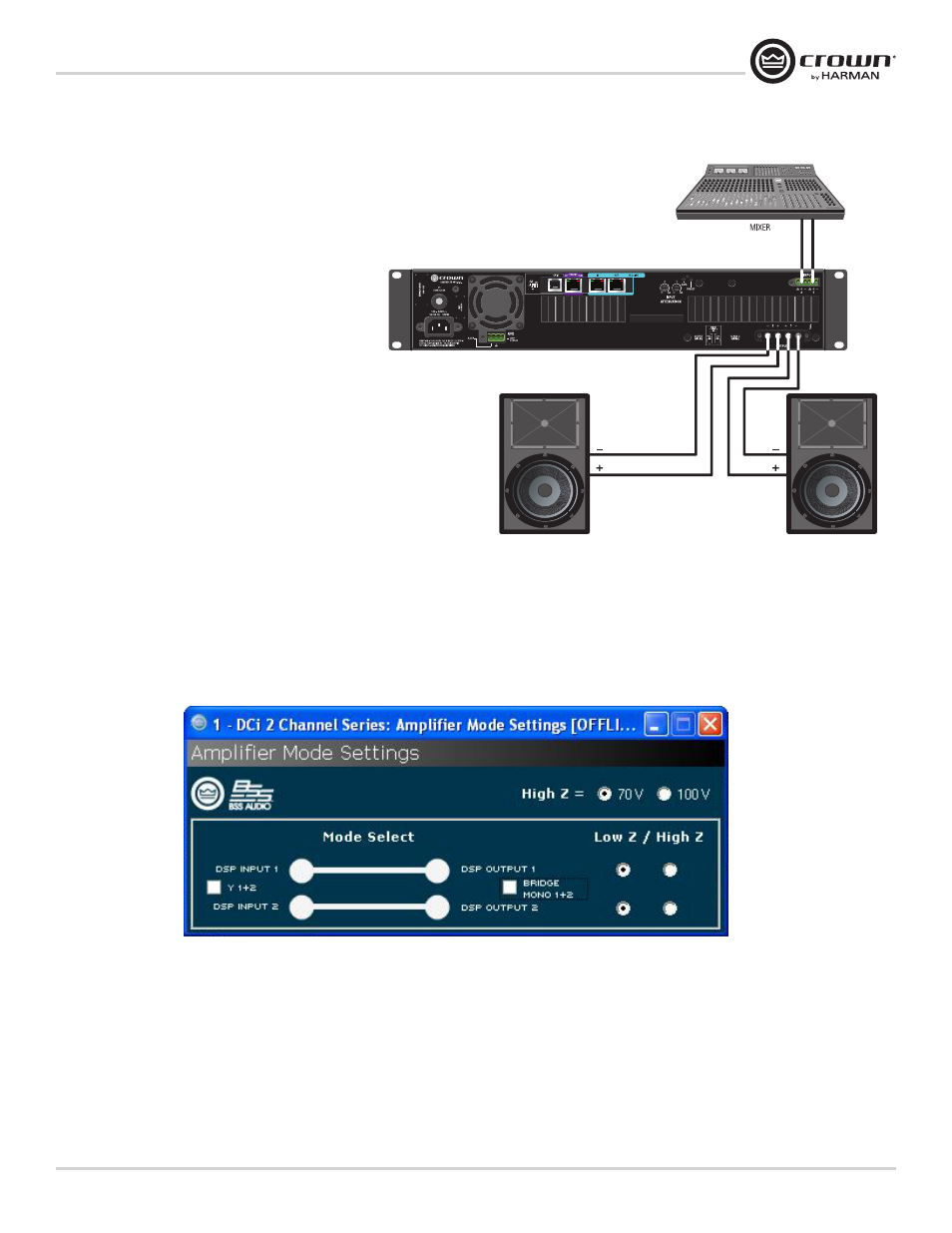
Low-Z (8, 4 or 2 Ohm) Output Operation
Typical input and output wiring, along with Audio Architect
software settings are shown in Figure 12.
INPUTS: Connect the input with wiring in place for each
channel. If the same signal is to drive both outputs of a
channel pair (“mono”), the input signal can be sent to
adjacent amplifier channels. If using the BLU Link input, it
is important to understand that BLU Link is a digital audio
bus and cannot be routed through a network switch or
router. To increase fault protection, use both the input and
output BLU Link wiring connection. For BLU Link routing,
refer to page 25.
OUTPUTS: Maintain proper polarity (+/–) on output
connectors. Connect the Channel 1 speaker’s positive (+)
lead to amplifier Channel 1 positive terminal;
repeat for negative (–). Repeat Channel 2 wiring as for
Channel 1, and for any subsequent channel pairs on
multichannel models. Refer to Page 8
for output connector terminal assignments.
Always route the input and output wires in separate bundles.
Figure 12 System Wiring Dual Mode
Figure 12