Installation instructions, Continued) – S&B Filters Cold Air Intake Kit - Cotton Filter 75-5020 User Manual
Page 2
8/21/2008
REV-A
PERFORMANCE TESTING
∗ Engage parking brake and start your
engine. Listen for abnormal noises. If an
air leak is detected, re-inspect hoses and
connections as they may need to be repo-
sitioned and tightened.
∗ S&B FILTERS RECOMMENDS THAT
YOU KEEP YOUR OEM INTAKE SYS-
TEM IN THE EVENT IT IS REQURIED IN
THE FUTURE.
∗ In order to maintain your warranty, all
connections and components must be
checked periodically for alignment and
for proper tension on all connections.
Failure to do so will void your warranty.
∗ Use only S&B Filter cleaning and oil prod-
ucts to service your filter. Using any other
brand oil and or cleaners may void your
warra
nty.
(909) 947-0015 Phone • (909) 947-0603 Fax
www.sbfilters.com
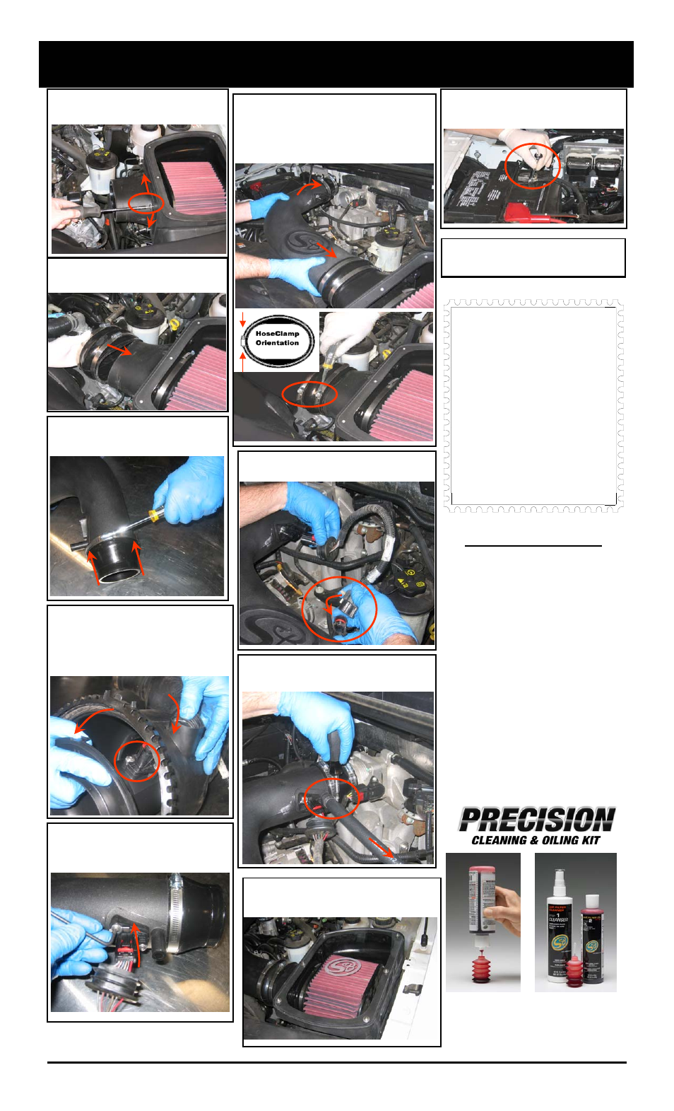
INSTALLATION INSTRUCTIONS
(continued)
9. Secure the S&B flange adapter (J) to the
S&B air box (O) with the four 5/16 SS Phillips
head screws (I) provided.
10. Place the Oval Hump adapter (H) over
the filter adapter (J), do not tighten hose
clamps at this step.
11. Install the 3.75”-2.45” adapter (E) to the
S&B tube (C) as shown, secure with # 60
hose clamp (D).
12. Remove the MAF sensor from the OE air
box; pull the rubber plug out then turn it side-
ways and push it through the hole, separate
the housing and using the #T-20 Torx wrench
supplied remove the MAF sensor.
Note: Direction of sensor related to air flow.
13. Install the MAF sensor into the S&B tube
(C). Secure with the OE screws, tighten
evenly and do not over tighten!
Note: Direction of sensor related to air flow.
14. Install the S&B tube (C) into the Oval hump
adapter (H) then onto the throttle body. Center
the Oval hump adapter (H) over gap between the
tube ends and secure with #88 hose clamps
(G) , then secure # 52 hose clamp (V) at throttle
body. Note: Position clamps as shown below.
15. Reconnect MAF sensor electrical connection.
Check that both connectors are fully engaged.
16. Install the S&B 5/8” crankcase vent hose (A)
from the valve cover to the S&B Intake tube (C),
secure both ends with #8 hose clamps (B).
17. Install the S&B clear lid (R), secure with
10/24 screws (S) and sealing washers (U).
Do not over tighten.
18. Reconnect the battery. Inspect your
installation, make sure kit is properly
positioned and all fasteners are secure.
19. Affix the C.A.R.B. exemption sticker in
plain sight under the hood near the intake
system.
Order online today at www.sbfilters.com
or though your local S&B Distributor
Part No. 88-0005
1.
1st
2nd
Smog Certification Note:
The California Air Resource Board
(CARB) requires that an E.O.
identification label be applied to the
vehicle in order to pass a smog
check inspection when a High
Performance Intake Kit has been
installed.
You must place the E.O. label
provided on or near the intake kit
after installation so that a smog
check technician can easily verify
the E.O. number.