Installation instructions, Vehicle application, Tools required – S&B Filters Snow Plug 75-5051 User Manual
Page 2: Before you start
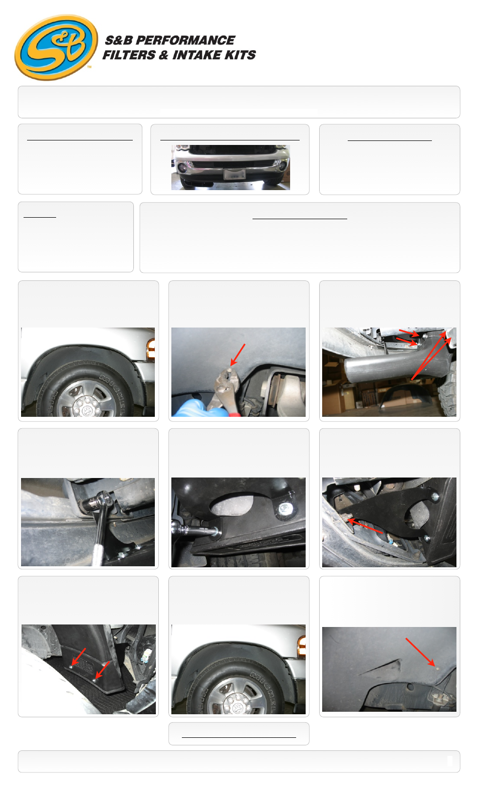
1.
Using a 8mm socket locate and remove
the (8) screws from the wheel well liner.
INSTALLATION INSTRUCTIONS
VEHICLE APPLICATION
Year: 2003-09
Make: DODGE
Model: RAM 2500/ 3500
Engine: 5.9L / 6.7L DIESEL
(Standard chrome bumper only)
TOOLS REQUIRED
• 8mm Socket
• 18mm Wrench & Socket
• 7/16” Wrench & Socket
• Pliers
STANDARD CHROME BUMPER ONLY
NOTES
Kit may not fit with the following:
• Painted or Aftermarket Bumper
• Aftermarket Parts installed
• Body Lift or Lowering Kit
• Custom Hood
• Oversized Wheels and Tires
BEFORE YOU START
• Please read the entire product guide before proceeding.
• Ensure all components listed on page 3 are present.
• If you are missing any of the components, call our customer support at (909) 947-0015.
• Do not attempt to work on your vehicle while engine is hot.
• Make sure the engine is turned off and the vehicle is in Park or the Parking Brake is set.
787 S. Wanamaker, Ontario, CA 91761 - Phone: (909) 947-0015 - Fax: (909) 947-0603 -
4.
From under the truck, remove the two nuts
behind the bumper on either side of the frame
using a 18mm socket. Slide the mounting
brackets off the studs and remove the scoop
base.
7.
Reinstall the two 1/4”-20 screws and
washers to the back of the scoop channel.
Double check to make sure all hardware is
secure and the system is properly positioned.
2.
Using a pair of pliers, push the pin
attaching the wiring harness to the inside.
Then remove the wheel well liner from vehicle
by pushing it in and then down to remove.
5.
Insert the Scoop plug
(A)
into the scoop
channel. Then attach the “L” bracket
(B)
to
the scoop channel using two of the 1/4”-20
screws and washers removed in step #3.
8.
Reinstall the wheel well liner using the (8)
screws that were removed in step #2. Make
sure all of the screws are started before
tightening them down.
3.
While supporting the scoop base remove
the four 1/4”-20 screws attaching the scoop
base to the scoop channel. Retain all the
hardware.
6.
Mount the front tab of the “L” bracket to
the stud on the bumper using the 18mm nut.
Tighten down both 18mm nuts to the back
side of the bumper to the OE torque specs.
P/N: 75-5051
SEE EXPLODED VIEW ON PAGE 3
2
Important: Read warning page prior to proceeding.
Two on opposite side
(Not shown)
9.
Push in the pin that was removed in step
#2 from inside the engine compartment.
Inspect the installation, be sure the kit is
properly positioned and all fasteners are
secure.