Installation instructions (continued) – S&B Filters Cold Air Intake Kit - Cotton Filter 75-5058 User Manual
Page 2
15461 Slover Ave., Fontana, CA 92337 - Phone: (909) 947-0015 - Fax: (909) 947-0603 -
Installation Instructions (continued)
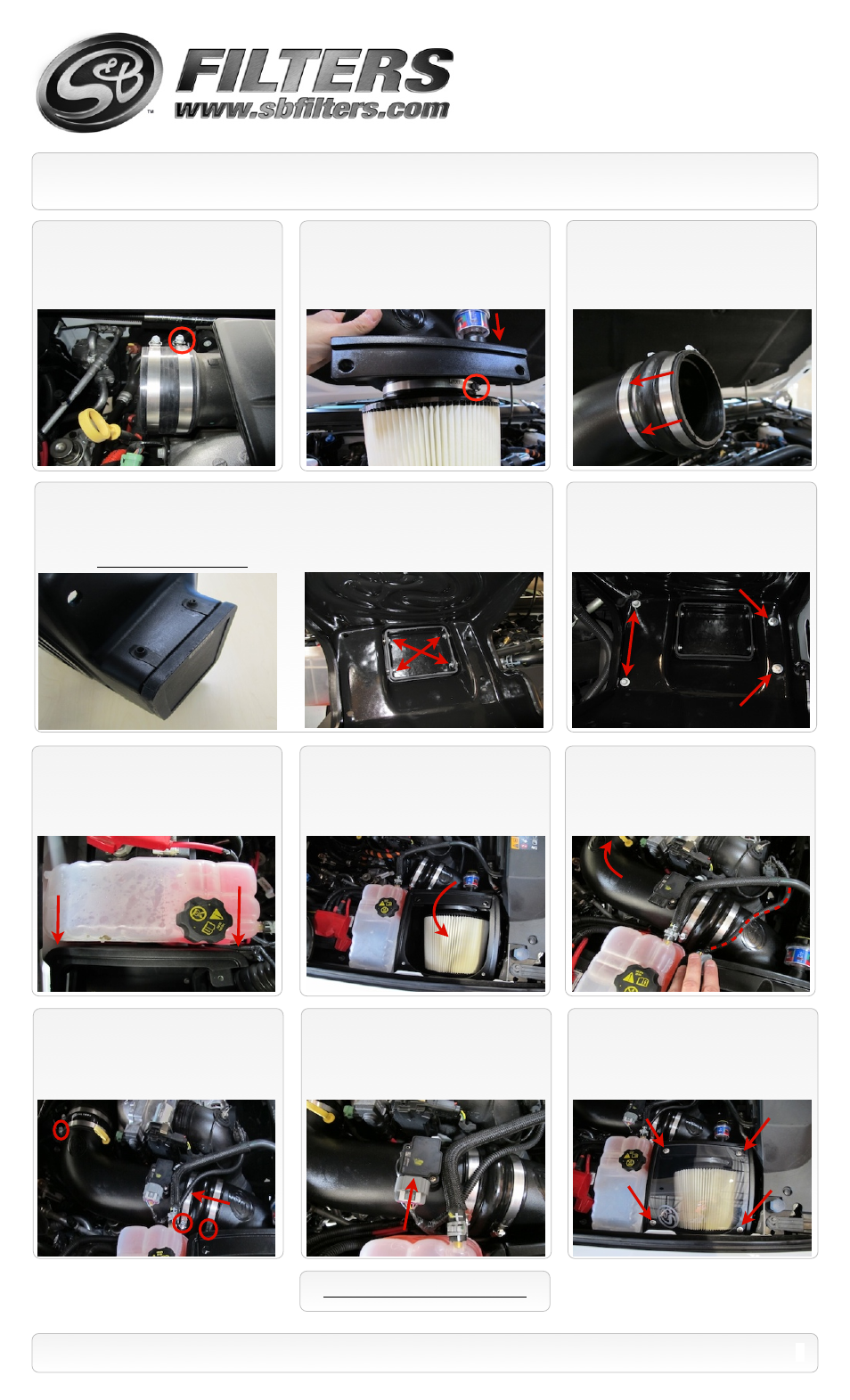
10.
Place the Silicone Adapter
(R)
and both
#72 Hose Clamps
(O)
onto the turbo inlet
mouthpiece. Tighten the clamp on the turbo
mouthpiece only.
12.
Slide the two #80 Hose clamps
(N)
over
the Hump Adapter
(M)
. Then push the Hump
adapter
(M)
over the Adapter tube
(D)
. Leave
clamps loose for now.
18.
Slide the Hump Adapter
(M)
over the
Intake Tube
(L)
. When satisfied with the
positioning, tighten the two #80 hose clamps
(N)
and #72 Hose clamp
(R)
at the turbo.
11.
Place the Adapter Tube
(D)
into the base
of the S&B Air Filter
(E)
and tighten the #96
Hose clamp
(F)
. Remove the Filter minder
and grommet from the OE air box lid, then re-
install them into the Adapter tube
(D)
.
14.
Move the coolant reservoir out of the way.
Install the Air Box
(A)
using the two supplied
M6x30mm screws
(C)
and 6mm Washers
(B)
for
the two holes closest to the fender. Use the OE
screws for the other two holes. Tighten all four.
15.
Reinstall the coolant reservoir
mounting hardware that was removed in
Steps #7 and #8.
19.
Reconnect the MAF sensor wiring
harness to the MAF sensor.
16.
Carefully place the filter assembly into
the Air Box (filter end first) trying not to ding or
gouge the filter element. Rotate the Filter
Adapter assembly into position and hook the
clip into the Air Box.
20.
Install the Clear Lid
(G)
using the supplied
5/16” S.S. Screws
(I)
and Rubber Washers
(H)
along with the 10-24 Screws
(K)
and SS Sealing
Washers
(J)
. This will secure the Filter Adapter to
the Air Box as well.
(Do not over tighten!)
SEE EXPLODED VIEW ON PAGE 4
2
P/N: 75-5058 / 75-5058D
17.
Route the MAF sensor wiring harness as
shown. Then install the Intake Tube assembly
into the Silicone adapter
(R)
.
13.
For those concerned about minimal engine heat; insert the four Clip Nuts
(S)
over the holes on
the bottom opening of the Air Box
(A)
, insert the Box Plug
(T)
into the end of the Air Box
(A)
. Attach
using the supplied 1/4-20 Hex Screws
(U)
and Flat Washers
(B)
from the inside of the Air box using
5/16” socket or ratcheting wrench. For those seeking additional air flow, set the Air Box End Cap
aside and save all the supplied hardware.
(See page 3 for more info)
O
E
Scre
w
s