Installation instructions (continued), Oe s&b 1 2 19 – S&B Filters Cold Air Intake Kit - Cotton Filter 75-5059 User Manual
Page 2
15461 Slover Ave., Fontana, CA 92337 - Phone: (909) 947-0015 - Fax: (909) 947-0603 -
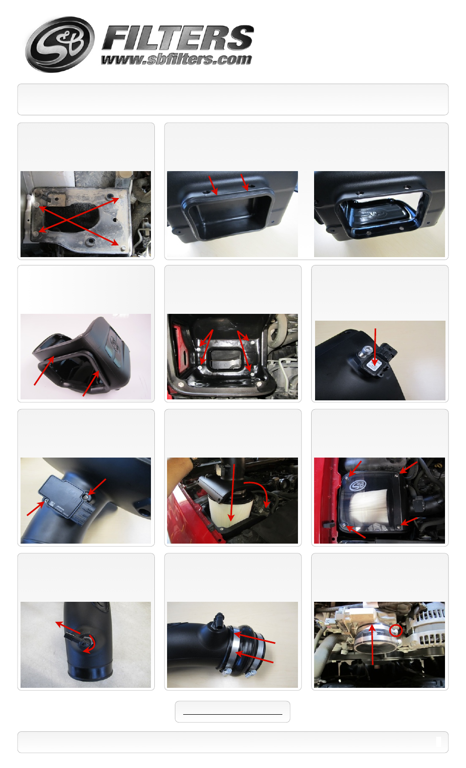
Installation Instructions (continued)
14.
If equipped with Pressure Sensor, Drill a
1/4” hole using the drill point located in the Filter
Adapter Tube
(K)
. Be careful only to drill through one
surface (NOT all the way through the backside).
Thoroughly clean the inside of the tube of all debris.
Then install the pressure sensor using the 1/4-20
Socket Screw
(L)
and a 3/16” allen wrench.
13.
Install the Air box assembly using the
supplied M6-1.0x10mm Screws
(T)
and 6mm
Washers
(U)
in the two holes closest to the
fender and the 2 longer OE screws in the
remaining two holes.
15.
Remove the MAF sensor from the OE
air cleaner using the supplied T15 Torx key.
Install it into the Filter Adapter Tube
(K)
using
the supplied 8-32x1/2” Screws
(J)
. Do not
over tighten.
16.
Insert the S&B Filter
(D)
onto the
Adapter Tube
(K)
and secure the #80 Hose
Clamp
(E)
. Install the assembly into the Air
box as shown below.
17.
Install the Clear Lid
(H)
. Secure the Lid and
Filter Adapter using the supplied 1/4”-20x1-1/4”
S.S. Screws
(I)
and Rubber Washers
(F)
. Then
use the 1/4”-20x5/8” S.S. Screws
(G)
and
Rubber Washers
(F)
in the remaining two holes.
2
18.
Install the 90degree Hose Barb
(P)
on to
the Intake Tube
(O)
until it is hand tight.
Then
using a 9/16” wrench turn it one more rotation
into position as shown.
11.
For those concerned about minimal engine heat; install the Air Inlet Plug
(A)
into the bottom of
the Air Box
(B)
by pushing it down until the bead catches the lip as shown below. For those seeking
additional air flow, set the Air Inlet Plug aside.
(See page 3 for more info and test results)
20.
Secure the Silicone Step Coupler
(S)
to
the throttle body using a #64 Hose Clamp
(M)
. Place the #72 Hose Clamp
(R)
around
the top of the Silicone coupler.
SEE EXPLODED VIEW ON PAGE 4
P/N: 75-5059 / 75-5059D
12.
Install the Air Inlet Fender Seal
(C)
onto
the lip of the Air Box
(B)
.
10.
Using 10mm socket, remove the 4
bolts securing the air box tray. Then remove
the tray from the truck. Save all 4 bolts for
S&B installation.
OE
S&B
1
2
19.
Place a #64 Hose clamp
(M)
over each
end of the Hump Coupler
(N)
. Then slide the
hump coupler over the end of the Intake Tube
(O)
.