Installation instructions (continued) – S&B Filters Cold Air Intake Kit - Cotton Filter 75-5045 User Manual
Page 2
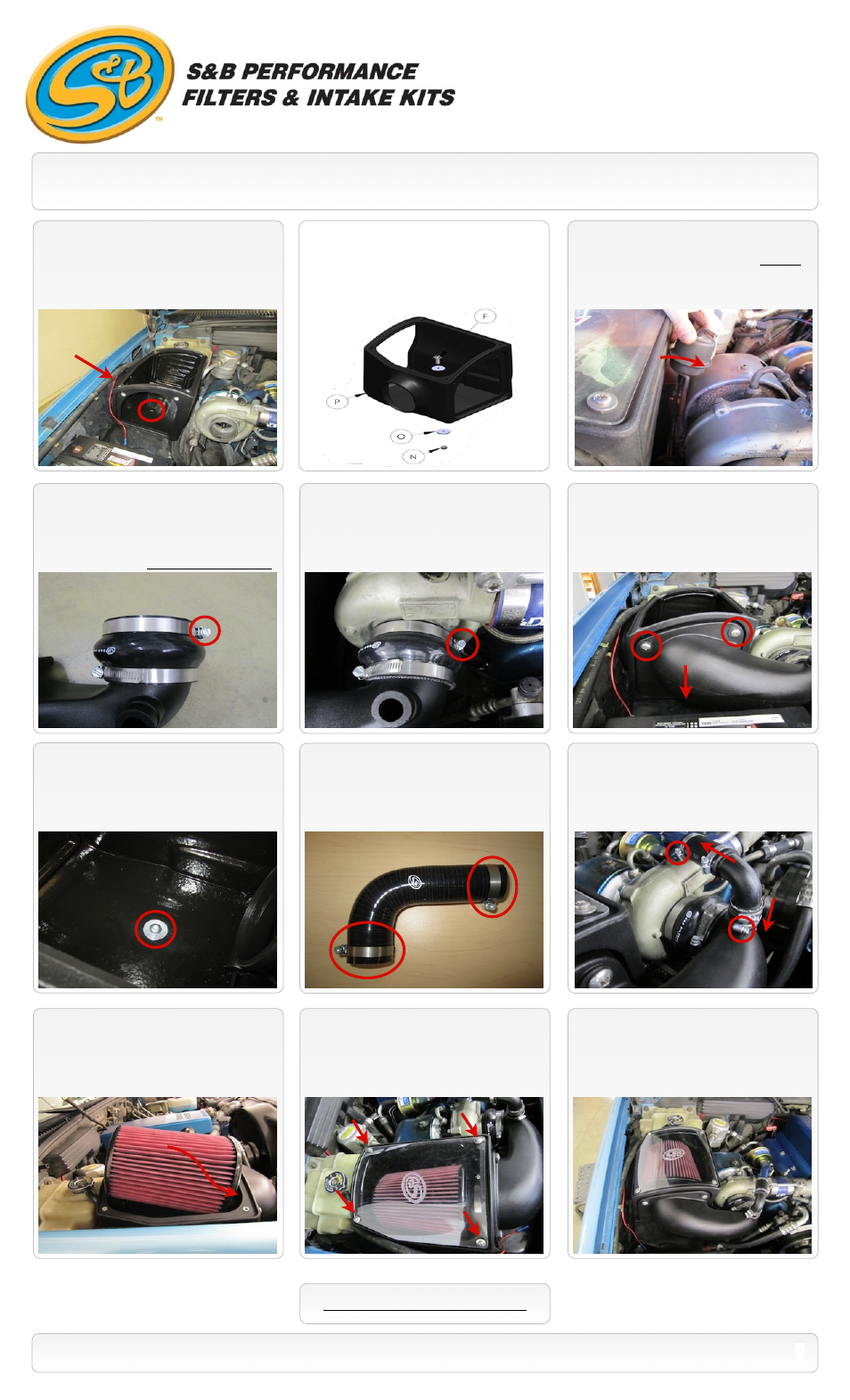
Note:
For C/K models 1996-00:
(If equipped) It may be necessary to carefully
bend the mounting tabs on waste gate
vacuum canister to clear the new Air Box.
13.
Install the intake tube assembly onto the
turbo first and tighten the #52 Hose Clamp
(G)
at the turbo.
14.
Hook the latch on the Intake Tube
(L)
to
the bottom edge of the Air Box
(P)
. Secure
the tube to the box using the 2 supplied 3/8”
Truss Screws
(M)
.
15461 Slover Ave., Fontana, CA 92337 - Phone: (909) 947-0015 - Fax: (909) 947-0603 -
INSTALLATION INSTRUCTIONS (Continued)
11.
Loosely install the Air Box
(P)
to the
wheel liner using the supplied 3/8”x1.0”
Button Head screw
(F)
and Fender Washer
(O)
on top and the 3/8” Nylock Nut
(N)
and
Fender Washer in the wheel well.
15.
When you are satisfied with the
positioning of the box, tighten the hardware
mounting the box to the wheel liner.
12.
Install the Silicone Turbo Adapter
(H)
to
the Intake Tube
(L)
. Install the larger ID end
on the tube using the #56 Hose clamp
(I)
.
Place the #52 Hose Clamp
(G)
on the smaller
end of the adapter. *Note the clamp position*
16.
Install the 2 #16 Hose Clamps
(J)
on
each end of the Silicone CVT Elbow
(K)
.
18.
Completely loosen the clamp
(E)
around the Air filter base. Then carefully place
the Air Filter
(D)
(base end first) inside the Air
Box
(P)
. Push the base of the filter over the
Intake Tube
(L)
and tighten the hose clamp.
19.
Remove the protective covering from the
Clear Lid
(C)
, then install the lid. Secure with
the 10/24” Screws
(A)
and Sealing Washers
(B)
. Do not over tighten.
SEE EXPLODED VIEW ON PAGE 4
2
P/N: 75-5045 / 75-5045D
20.
Inspect your installation, make sure the
kit is properly positioned and all fasteners are
secure. Affix the CARB sticker near the
intake kit. The installation is now complete.
17.
With the 2 #16 Hose Clamps in place,
slip the longer hose end of the assembly onto
the OE vent tube and then push the smaller
hose end onto the intake tube. Fully tighten
the all hose clamps.
Small ID
Large ID
10.
Place the Air Box
(P)
into the truck. Line
the hole in the bottom of the box to the hole
on top of the wheel liner. Position the air inlet
of the box into the hole in the fender.