High density dc-dc modules, Electrical specification, Pin connection external output trim – Powersolve PS50 Series User Manual
Page 2
Powersolve Electronics Ltd. Units 8A, Arnhem Road, Newbury, RG14 5RU. England
Tel:01635 521858 Fax: 01635 523771 Email: [email protected]
www.powersolve.co.uk
High Density DC-DC Modules
INPUT
Input Voltage Range
12V
9-18V
24V
18-36V
48V
36-75V
Undervoltage lockout
12Vin power up
8.8V
power down
8V
24Vin power up
17V
power down
16V
48Vin power up
34V
power down
32.5V
Positive Logic Remote ON/OFF
3.4
Input Filter
Pi Type
OUTPUT
Voltage Accuracy :
+1% max.
Transient Response : 25% Step Load Change
<500
µ
sec.
External Trim Adj. Range
+10%
Ripple & Noise, 20MHz BW,
2.5V & 3.3V & 5V
20mV RMS., max. 75mV pk-pk, max.
12V & 15V
30mV RMS., max. 100mV pk-pk, max.
24V
100mV RMS., max. 240mV pk-pk, max.
ENVIRONMENTAL
Temperature Coefficient
+0.03%/°C
Short Circuit Protection
Continuous
Line Regulation
1
+0.2% max.
Load Regulation
2
+0.2% max.
Over Voltage Protection trip Range, % Vo nom.
115-140%
Current Limit
110% ~150% Nominal Output
GENERAL
Efficiency
See Table
Isolation Voltage
Input/Output
1500VDC min.
Input/Case
1500VDC min.
Output/Case
1500VDC min.
Isolation Resistance
10
7
ohm min.
Switching Frequency
12/24Vin
400KHz, Typ.
48Vin
300KHz, Typ.
Operating case Temperature
-40°C to 100°C
Storage Temperature
-55°C to +105°C
Thermal Shutdown, Case Temp.
100°C Typ.
Dimensions
2.28x2.40x0.50 inches
(57.9x61.0x12.7 mm)
Case Material
Aluminium
Electrical Specification
NOTE:
1. Measured From High Line to Low Line. 2. Measured From Full Load to Zero Load. 3. Logic Compatibility - Open Collector Ref. to -Input,
Module ON - Open Circuit, Module OFF - < 0.8Vdc 4. Suffix "N" to the Model Number with Negative Logic Remote ON/OFF.
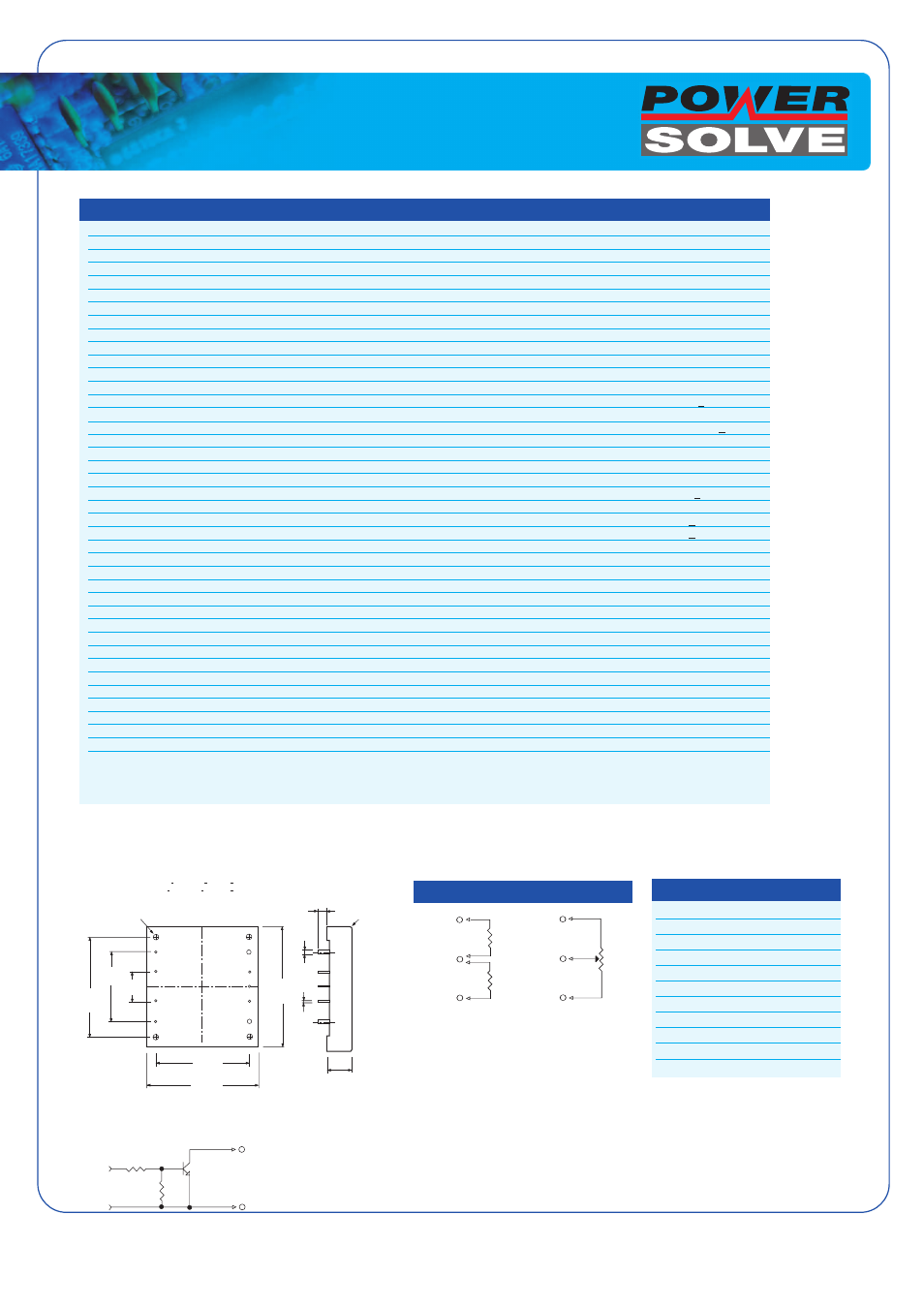
Pin Function
1
+Vin
2
ON/OFF
3
CASE
4
-Vin
5
-Vout
6
-Sense
7
Trim
8
+Sense
9
+Vout
Pin Connection
External Output Trim
2.40
(61.00)
Ø0.08
(2.03)
2pl.
0.50
(12.70)
0.18 min.
(4.60 )
2*R1.50
Mounting Inserts
M3*0.5 Through 4pl.
2.00
(50.80)
1.40
(35.56)
0.60
(15.24)
4
3
2
1
5
6
7
8
9
1.90
(48.25)
2.28
(57.90)
Ø0.04
(1.02)
7pl.
All Dimensions In Inches(mm)
-SENSE (6)
TRIM UP
TRIM (7)
TRIM DOWN
+SENSE (8)
-SENSE (6)
+SENSE (8)
TRIM (7)
10K ohms
TRIMPOT
HIGH SIGNAL HERE
DISABLE OUTPUT
ON/OFF (2)
-VIN (4)
Pin
Tolerances
Inches
.XX +.02 .XXX+.01 +0.02
Millimeters
.X+.5 .XX+.25
+0.5
Remote ON/OFF Control
BOTTOM VIEW
SIDE VIEW
All Specifications Typical At Nominal Line, Full Load and 25°C Unless Otherwise Noted.
2