Powersolve UMS Series User Manual
Page 2
Powersolve Electronics Ltd., Unit 8A Arnhem Road, Newbury RG14 5RU, United Kingdom
Tel 0044 (0)1635 521858 Fax 0044 (0)1635 523771
www.powersolve.co.uk
p.2/3 03.12B
(Subject to alterations. This product is not designed to be used in applications such as life support systems wherein a failure or malfunction could result in injury or death)
DC-Input
24Vdc ± 20%
Input Rating
typ. 100mA
Model
UMS00025.10T
UMS00025.15T
UMS00025.20T
UMS00050.20T
UMS00050.30T
UMS00050.40T
Rated Voltage
60V
40V
30V
60V
40V
30V
Rated Current
10A
15A
20A
20A
30A
40A
Boost
≤
10ms
40A
60A
80A
80A
120A
160A
Model
UMS00100.80T
UM00100.60T
UMS00100.40T
UMS00100.20T
Rated Voltage
30Vdc
40Vdc
60Vdc
120Vdc
Rated Current
80A
60A
40A
20A
Boost
≤
10ms
320A
240A
100A
80A
Input-/output voltage error sequence: +20% for < 60 sec. (safety: >60Vdc we advise to use ADTW201 for galvanic insulation)
Cooling
Natural convection
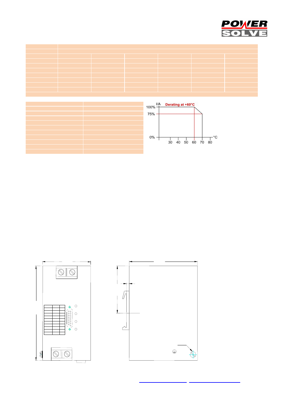
Ambient Temperature
-20°C...+70°C
Storage Temperature
-40°C...+85°C
EMI
EN55022 class B
Safety
cUL60950/1950 EN60905-1
Safety Class 1
VDE0805, VDE0100
MTBF (IEC61709)
500.000h at 45°C
Screw terminals
AWG16 - AWG4 (1.5...20mm²)
Controller connector
SUB-D15 (IEC)
Dimensions (HxWxD)
124x65x96
Weight
990g
Terminal Connects:
Input
DC+
DC-
Output
DC-out 1
DC-out 2
Power supply
24Vdc +
24Vdc –
SubD pinout control I/O:
1 = right input
+24Vdc 5mA max.
2 = left input
+24Vdc 5mA max.
3 = stop
+24Vdc 5mA max.
4 = GND of PIN 1,2,3
5 = sense input +
6 = sense input –
7 = sense output +
8 = sense output –
9 = control right
+24V 10mA typ.
10 = control left
+24V 10mA typ.
11 = GND 9,10
12 = not connected
13 = not connected
14 = not connected
15 = not connected
Screw terminal order codes: SK2 Art.No.: 3520037
(each package = 10 pcs ) (1pc needed for 24V supply)
Technical information:
Right Input: A positive signal will connect the input (+) to DC-Out1
and input (-) to DC-out1. The control-LED RIGHT lights.
Left Input: A positive signal will connect the input (+) to DC-Out2
and input (-) to DC-out2. The control-LED LEFT lights.
Left/Right Input: If a positive signal is emitted to both inputs at the
same time or if no signal is emitted, the DC-Outputs are disabled
and the Master-Stop-LED lights.
Stop Input: A positive signal must be emitted to the input to run all
functions. The Stop-Input can also be used as an emergency stop
switch. The output will be switched off either there is no signal
emitted or it is at 0 volts; the Master-Stop-LED lights.
Sensing: While using the sense connections for line compensation
the used wires must be twisted pair to avoid radiated emissions.
The cables should be closed directly at the consumer load inputs. It
is recommended to use a 100uF bipolar in combination with a
100nF ceramic capacitor.
65,0
UMS
electronic DC-load switch
124,0
3,5
96.0
62,0
DC-Input
+
-
DC-Output
1
2
Right
Left
Stop
Power
+
-
24VDC
M4
V
A
60
10
40
15
30
20
60
20
40
30
30
40
120
20
60
40
40
60
30
80