Ac-dc converters, Pin connections – Powersolve JB200 Series User Manual
Page 2
www.powersolve.co.uk
Powe rsolve Electronics Ltd. 8A, Arnhem Road, Newbury, RG14 5RU. England
Tel:01635 521858 Fax: 01635 523771 Email: [email protected]
AC-DC Converters
Max. Output Power or Current
Model
Output Range
Preset
With Forced Air
Convection
Regulation
Ripple & Noise
Voltage
JB200-3v3
3 ~ 4V
3.3V
30A
22A
+/- 1%
+/- 1%
JB200-05
5 ~ 6V
5V
200W
22A
+/- 1%
+/- 1%
JB200-12
12 ~ 18V
12V
200W
150W
+/- 1%
+/- 1%
JB200-24
24 ~ 30V
24V
200W
150W
+/- 1%
+/- 1%
JB200-48
48 ~ 56V
48V
200W
150W
+/- 1%
+/- 1%
JB200-36
32 ~ 46V
36V
200W
150W
+/- 1%
+/- 1%
OUTPUT VOLTAGE/CURRENT RATING CHART: Measured at output power connector
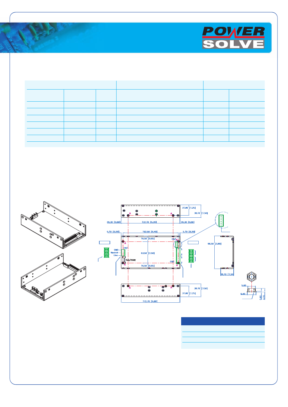
OUTLINE DRAWING: Overall size: 6.8(L) x 3.8(W) x 1.5(H)inches; Weight: 600g. (Optional Top Cover)
NOTES:
AC Input Connector (CN1): Mating Molex Part No. 09-91-0500 or equivalent (5 pin,3 used)
PCB is Labeled: L = Line; N = Neutral; G = Chassis Ground Mating Pins; Molex Engineering
Series 2478, 2578, 8818 or Howder Terminal block Part No. FTB-702-3P (3 pin).
Output Connector (CN2): Mating Molex Part No. 09-91-1200 (12 pin), or Howder Terminal
block Part No. HD-301-4P (4 pin).
Output Pin Assignment: (See table in right).
Logic signal connector (CN3):
Mating JST XHP-6 or equivalent (CHYAO SHIUNN JS-2001-06).
Mating Pins: JST SXH-002T-P0.6 FOR AWG 30 to 26.
Mounting Inserts: 8 Places M4. Maximum Penetration 4mm see outline drawing for location.
Notes:
* The output ranges above are covered in safety agencies certification and the preset voltage will be factory set as standard models. For other voltages
contact sales office.
* 1% minimum load is required to maintain the ripple and regulation.
* Maximum 200W continuous output, with minimum 18.7 cfm forced ventilation.
* Maximum 150W continuous output with air convection, except 3.3V & 5V models which are power limited to 22A.
* Ripple and noise is measured from 10KHZ to 20MHz bandwidth at output terminals with parallel 0.1uF ceramic and 22uF electrolytic capacitors.
* All models can be used for N+1 redundancy.
VO-
VO+
VO-
VO+
INPUT
OUTPUT
TERMINAL BLOCK
M3 SCREW PINS
7.62mm CENTRE
(Part No. FTB-702-3P)
TERMINAL BLOCK
(PART NO. HD-301-4P)
M3.5 SCREW 4PINS,
11mm CENTRE
MATING: MOLEX P/N,
09-91-0500 (5PINS)
PINS 2, 4 NC
MOLEX PART NO. 09-91-1200 (12 PINS)
HOUSING PITCH 2.5mm
(MATING: JS-2001-06 OR EQU.)
RTN
REMO
PG
RTN
FAN-
FAN+
A: MOUNTING HOLE
SCALE 4:1 (8X) BRESS
M4XO.7
Molex Howder
VO- : Pins 7 ~ 12
VO- : Pins 3 ~ 4
VO+ : Pins 1 ~ 6
VO+ : Pins 1 ~ 2
Pin Connections