Ups cabinet – Powersolve XC Series User Manual
Page 2
www.powersolve.co.uk
Powersolve Electronics Ltd. 8A, Arnhem Road, Newbury, RG14 5RU. England
Tel:01635 521858 Fax: 01635 523771 Email: [email protected]
F
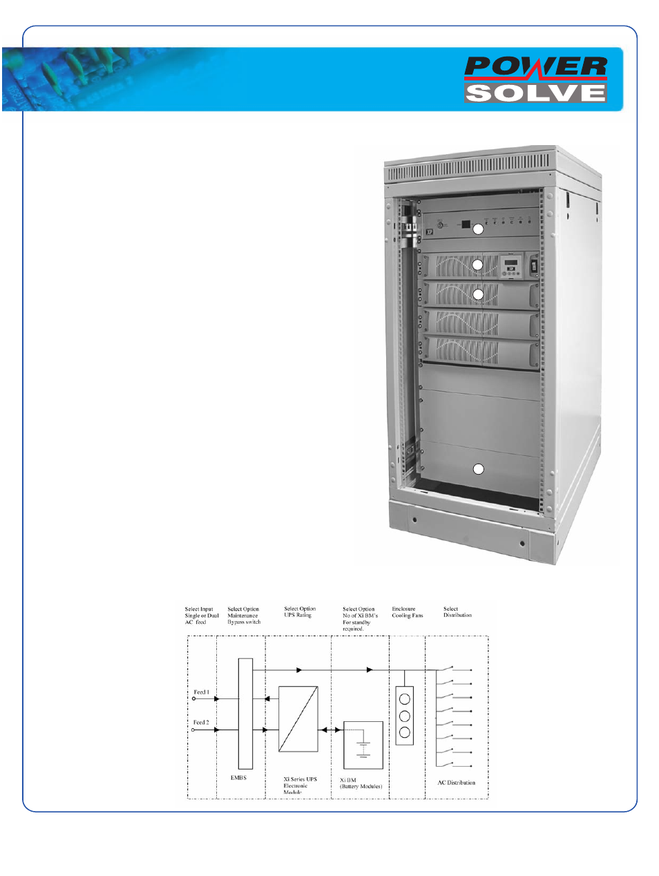
Section A
The top section of the cabinet houses the intergraded cooling fans and
optional Maintenance Bypass Switch Panel when fitted.
Section B
Xi series UPS Electronic module complete with Liquid Crystal Display
(LCD) provided information on
Information available from LCD:
•
Input Voltage: VAC
•
Output Frequency: Hz
•
Output Voltage: VAC
•
Battery Voltage: VDC
•
Load: %
•
Ambient Temperature: ºC
•
Internal Heatsink Temperature: ºC
•
Output Current: A
Section C
This section holds the battery modules (Xi BM), the number of Xi BM’s
fitted will depend on the battery capacity required for each application
and the autonomy required on utility fail.
Each additional string of Xi BM adds 7Ah to the battery capacity of
the system.
Section D
Behind the these blanking panels can be found the customer interface -
Input/Output and alarm terminal blocks - Breakers are provided for AC
input isolation along with any customer specific distribution circuits
Notes
1. General assembly may change due to system configuration.
A
B
C
D
Product Description
Schematics
13-April-09
UPS CABINET