Warning, Fg g c f – Peerless-AV PCC-S - Installation User Manual
Page 6
6 of 24
ISSUED: 04-23-08 SHEET #: 120-9046-3 09-28-12
Visit the Peerless Web Site at www.peerless-av.com
For customer care call 1-800-865-2112
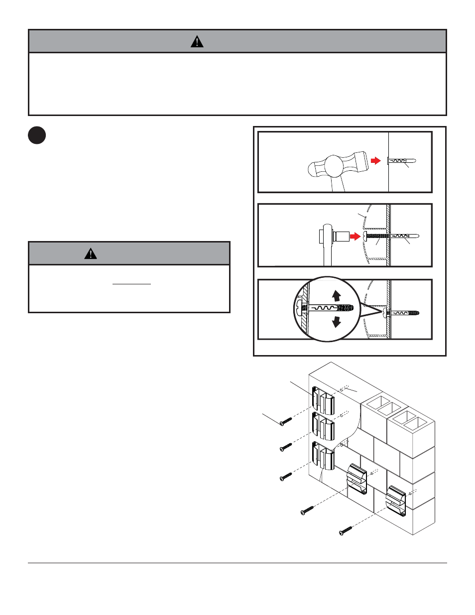
Make sure that mounting base (C) pilot holes are
level. Drill 1/4" (6 mm) dia. holes to a minimum depth
of 1.5" (64 mm) for each mounting base. Insert
anchors (F) in holes fl ush with mounting surface as
shown (right). Place mounting base over anchor and
secure with #8 x 1" phillips screws (G). Level, then
tighten all fasteners.
NOTE: Head of anchor must touch mounting
surface.
NOTE: Be certain channel fl anges on mounting
bases are in the orientation as in fi g. 3.1 and 3.2 of
page 5 for left or right confi guration.
Installation to Solid Concrete or Cinder Block
3
mounting
surface
1
3
2
F
Drill holes and insert anchors (F).
Place base (C)
over anchors (F) and secure with screws (G).
Tighten all fasteners.
C
• Tighten screws so that mounting bases are fi rmly
attached, but do not overtighten. Overtightening can
damage screws, greatly reducing their holding power.
• Never tighten in excess of 25 in. • lb (2.5 N.M.).
WARNING
F
G
G
C
F
solid concrete
cinder block
• When installing Peerless mounting bases on cinder block, verify that you have a minimum of 1-3/8" of actual con-
crete thickness in the hole to be used for the concrete anchors. Do not drill into mortar joints! Be sure to mount in a
solid part of the block, generally 1" minimum from the side of the block. Cinder block must meet ASTM C-90 specifi -
cations. It is suggested that a standard electric drill on slow setting is used to drill the hole instead of a hammer drill
to avoid breaking out the back of the hole when entering a void or cavity.
WARNING