Detail 1, Placement and orientation of covers – Peerless-AV PCC-S - Installation User Manual
Page 4
4 of 24
ISSUED: 04-23-08 SHEET #: 120-9046-3 09-28-12
Visit the Peerless Web Site at www.peerless-av.com
For customer care call 1-800-865-2112
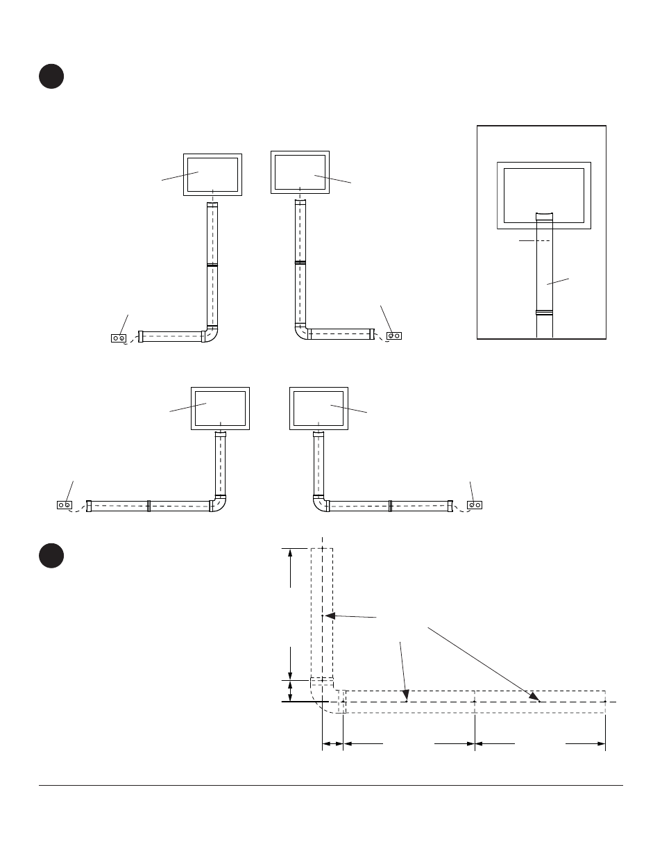
1
Determine location and confi guration of cable management that best routes cables from component to outlets.
Example of confi gurations are shown below. Cable management covers (A) can be cut for a desired length as
shown in detail 1.
NOTE: It is recommended that a hacksaw be used in order to cut cable covers to desired length prior to installation.
VERTICAL RIGHT CONFIGURATION
HORIZONTAL RIGHT CONFIGURATION
SCREEN
VERTICAL LEFT CONFIGURATION
HORIZONTAL LEFT CONFIGURATION
SCREEN
SCREEN
SCREEN
OUTLET
OUTLET
OUTLET
OUTLET
CAN BE
CUT FOR
DESIRED
LENGTH
DETAIL 1
Using a level, draw a vertical line
indicating the center of the covers
in the vertical orientation. Mark
mounting holes on the centerline
down the length of covers (if covers
are not cut, length will be 18").
If routing cables to left or right,
draw a level horizontal line 3"
(76 mm) below the last vertical
mounting hole. Mark the center
of the fi rst horizontal mounting
hole 3" (76 mm) to the left or right
depending on orientation.
Mark mounting holes between
vertical and horizontal mounting
holes.
2
18"
OR
LENGTH
OF CUT
COVER
3"
(76 mm)
3"
(76 mm)
MARK
BETWEEN
MOUNTING
HOLES
A
18"
OR LENGTH
OF CUT
COVER
18"
OR LENGTH
OF CUT
COVER
Placement and Orientation of Covers