Rs-422/485 serial connections, Table 5 - rs-422/485 signals on db-9 connector – B&B Electronics ESU2-400 - Manual User Manual
Page 17
USB-to-Serial Adapter User’s Manual
Making external connections
Rev 1.01 (February 2007)
Page 13
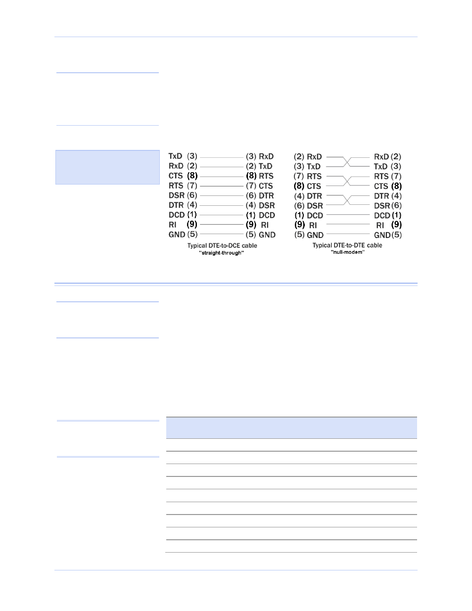
DTE- and DCE-type devices have complementary pinouts that allow
terminals and modems to connect directly using a one-to-one cable as
shown in Figure 14. Two DTE-type devices can be connected by a
null modem cable. A typical null modem cable is also shown in the
figure.
Figure 14 - Cabling requirements for RS-232 devices
RS-422/485 serial connections
The USB-to-Serial adapters provide four differential communication
signals (either RS-422 or RS-485) per channel. Transmit Data (TxD)
and Auxiliary Output (AuxOut) are the two output signals. Receive
Data (RxD) and Auxiliary Input (AuxIn) are the two input signals.
The adapters also provide a ground signal.
The AuxOut pair can carry the UART’s RTS signal. The AuxIn pair
can carry the UART’s CTS signal. Alternatively, the AuxOut pair can
be configured to internally loopback to the AuxIn pair, with the
UART’s RTS signal also looped back to its CTS signal. The following
table shows the RS-422/485 connector definitions.
Table 5 - RS-422/485 signals on DB-9 connector
RS-422/485 signal description
four-wire mode
DB-9 RS-422/485 signal description
two-wire mode
Auxiliary Input (AuxIn–)
1
DNC
Receive Data (RxD+)
2
DNC
Transmit Data (TxD+)
3
Transmit/Receive Data (Data+)
Auxiliary Output (AuxOut–)
4
DNC
Signal Ground (GND)
5
Signal Ground (GND)
Receive Data (RxD–)
6
DNC
Auxiliary Output (AuxOut+)
7
DNC
Auxiliary Input (AuxIn+)
8
DNC
Transmit Data (TxD–)
9
Transmit/Receive Data (Data–)
Figure 14 illustrates the RS-
232 pinouts for typical DTE-
to-DCE and DTE-to-DTE
cables with 9-pin connectors.
Note: In many applications,
DCEs are unnecessary. This
allows you to use a null modem
cable (modem eliminator cable)
to directly connect two DTE-
type devices.
Note: Pins labeled DNC (Do
Not Connect) are indeterminate
in two-wire mode and should be
left unconnected.
Note: Refer to Advanced
Options using Device Manager
for details on software-
selectable advanced options.