Making external connections, Rs-232 serial connections, Figure 12 - db-9 connector pinout – B&B Electronics ESU2-400 - Manual User Manual
Page 16: Table 4 - rs-232 signals on db-9 connector
Making external connections
USB-to-Serial Adapter User’s Manual
Page 12
Rev 1.01 (February 2007)
Making external connections
The USB-to-Serial adapters are equipped with male DB-9 connectors.
The following figures and tables show the serial port pinouts for RS-
232 and RS-232/422/485 applications.
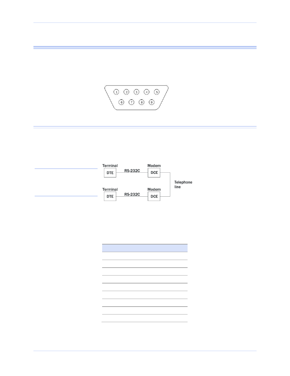
Figure 12 - DB-9 connector pinout
RS-232 serial connections
RS-232 devices are classified by their function as either Data
Terminal Equipment (DTE) or Data Communication Equipment
(DCE).
Figure 13 - Use of DTEs and DCEs in a communication link
The USB-to-Serial adapters are DTE devices that connect to
peripheral equipment through a male DB-9 connector. The following
table lists the serial port connector definitions.
Table 4 - RS-232 signals on DB-9 connector
RS-232 signal description
DB-9
Data Carrier Detect (DCD)
1
Receive Data (RxD)
2
Transmit Data (TxD)
3
Data Terminal Ready (DTR)
4
Signal Ground (GND)
5
Data Set Ready (DSR)
6
Request To Send (RTS)
7
Clear To Send (CTS)
8
Ring Indicator (RI)
9
Note: A DTE device is the
communication source. A DCE
device provides a communication
channel between two DTE-type
devices.