Combination mode 11: burst modulation 1, Atar862-3, Figure 87 – Rainbow Electronics ATAR862-3 User Manual
Page 85: Figure 88, Figure 89, Frequency measurement, Event counter with time gate, Burst modulation 1
85
ATAR862-3
4556B–4BMCU–02/03
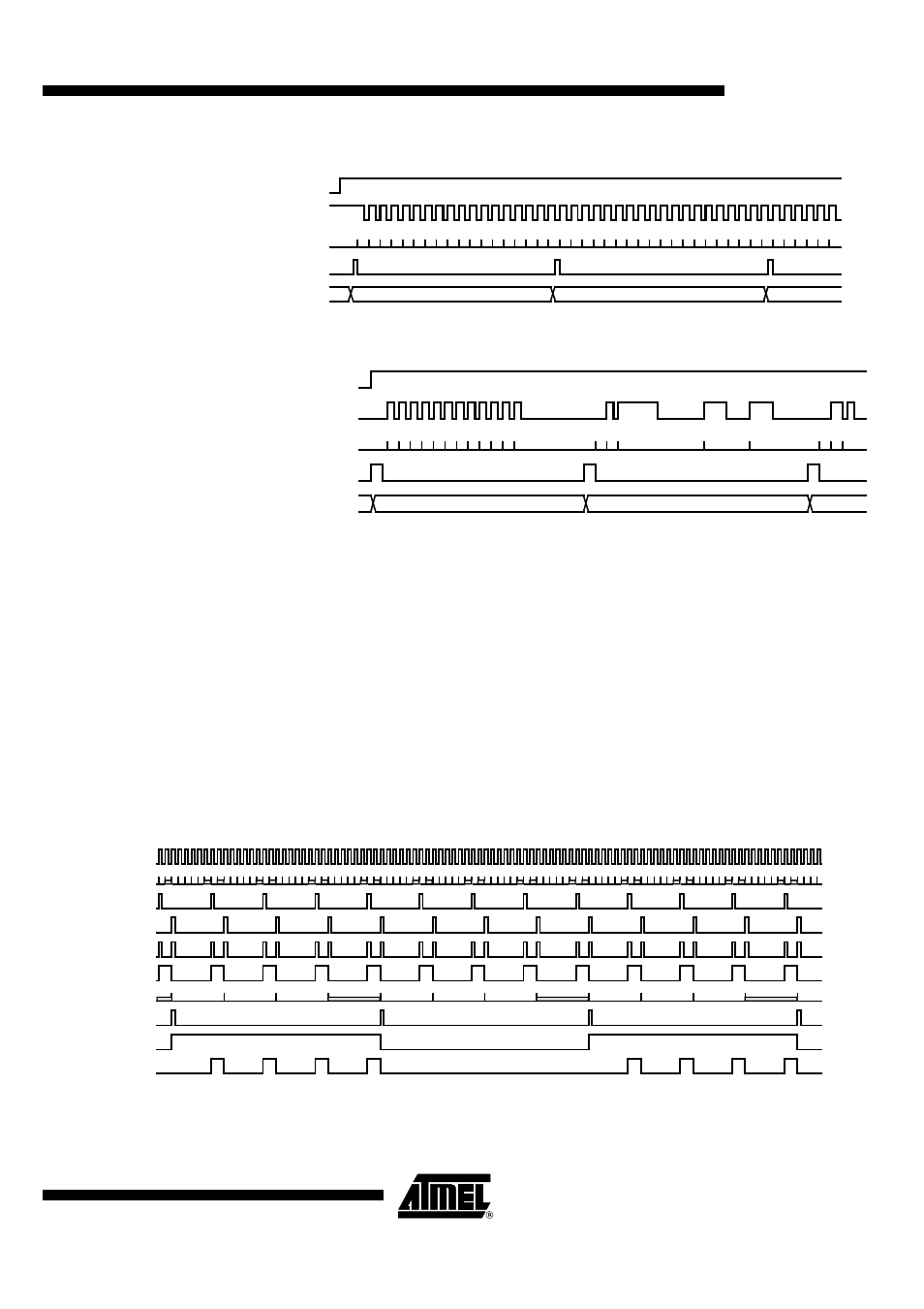
Figure 87.
Frequency Measurement
Figure 88.
Event Counter with Time Gate
Combination Mode 11:
Burst Modulation 1
Timer 2 mode 1/2:
12-bit compare counter/8-bit compare counter and
4-bit prescaler
Timer 2 output mode 1/6: Timer 2 compare match toggles the output flip-flop (M2)
to the Timer 3
Timer 3 mode 6:
Carrier frequency burst modulation controlled by Timer 2
output (M2)
The Timer 3 counter is driven by an internal or external clock source. Its compare and
compare mode registers must be programmed to generate the carrier frequency with
the output toggle flip-flop. The output toggle flip-flop (M2) of Timer 2 is used to enable
and disable the Timer 3 output. The Timer 2 can be driven by the toggle output signal of
Timer 3 (TOG3) or any other clock source.
Figure 89.
Burst Modulation 1
0 0 1 2 3 4 5 6 7 8 9 10
Counter 3
TOG2
T3CP-
Register
T3I
T3R
Capture value = 0
Capture value = 17
Capt. value = 18
11121314151617
1 2 3 4 5 6 7 8 9 101112131415161718
0
0 1 2 3 4 5
0 0 1 2 3 4 5 6 7 8 9 10
Counter 3
TOG2
T3CP-
Register
11
0 1
2
4
0 1
T3I
2
3
T3R
Capture value = 0
Capture value = 11
Cap. val. = 4
0 1 0 1 2 3 4 5 0 1 0 1 2 3 4 5 0 1 0 1 2 3 4 5 0 1 0 1
5 0 1 0 1
5 0 1 0 1
5 0 1 0 1
5 0 1 0 1
5 0 1 0 1
5 0 1 0 1
5 0 1 0 1
5 0 1 0 1
5 0 1 0 1
3
0
1
2
3
3
0
1
3
2
CL3
Counter 3
CM1
CM2
TOG3
M3
Counter 2/2
TOG2
M2
T3O