Combination mode 9: biphase demodulation, Atar862-3, Figure 84 – Rainbow Electronics ATAR862-3 User Manual
Page 83: Figure 85
83
ATAR862-3
4556B–4BMCU–02/03
Figure 84.
Manchester Demodulation
Combination Mode 9:
Biphase Demodulation
SSI mode 1:
8-bit shift register internal data input (SI) and the internal shift clock
(SCI) from the Timer 3
Timer 3 mode 11: Biphase demodulation with Timer 3
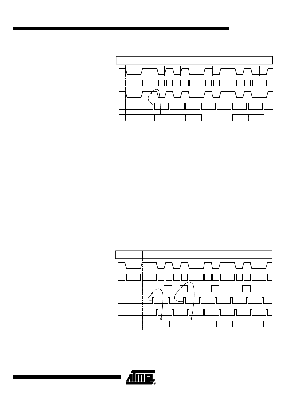
In the Biphase demodulation mode the timer works like in the Manchester demodulation
mode. The difference is that the bits are decoded with the toggle flip-flop. This flip-flop
samples the edge in the middle of the bitframe and the compare register 1 match event
shifts the toggle flip-flop output into shift register. Before activating the demodulation the
timer and the demodulation stage must be synchronized with the bitstream. The
Biphase code timing consists of parts with the half bitlength and the complete bitlength.
The synchronization routine must start the demodulator after an interval with the com-
plete bitlength.
The counter can be driven by any internal clock source and the output T3O can be used
by Timer 2 in this mode.
Figure 85.
Biphase Demodulation
1
0
1
1
1
0
0
1
1
0
1
1
Bit 7
Bit 6
Bit 5
Bit 4
Bit 3
Bit 2
Bit 1
Synchronize
Manchester demodulation mode
Timer 3
mode
T3EX
SI
SR-DATA
T3I
CM31=SCI
1
0
0
1
1
0
Bit 0
0
1
1
1
1
0
1
Bit 7
Bit 6
Bit 5
Bit 4
Bit 3
Bit 2
Bit 1
Synchronize
Biphase demodulation mode
Timer 3
mode
T3EX
Q1=SI
CM31=SCI
SR-DATA
0
0
0
0
T3I
Reset
Counter 3
1
0
1
0
1
0
Bit 0