Atar862-3 – Rainbow Electronics ATAR862-3 User Manual
Page 32
32
ATAR862-3
4556B–4BMCU–02/03
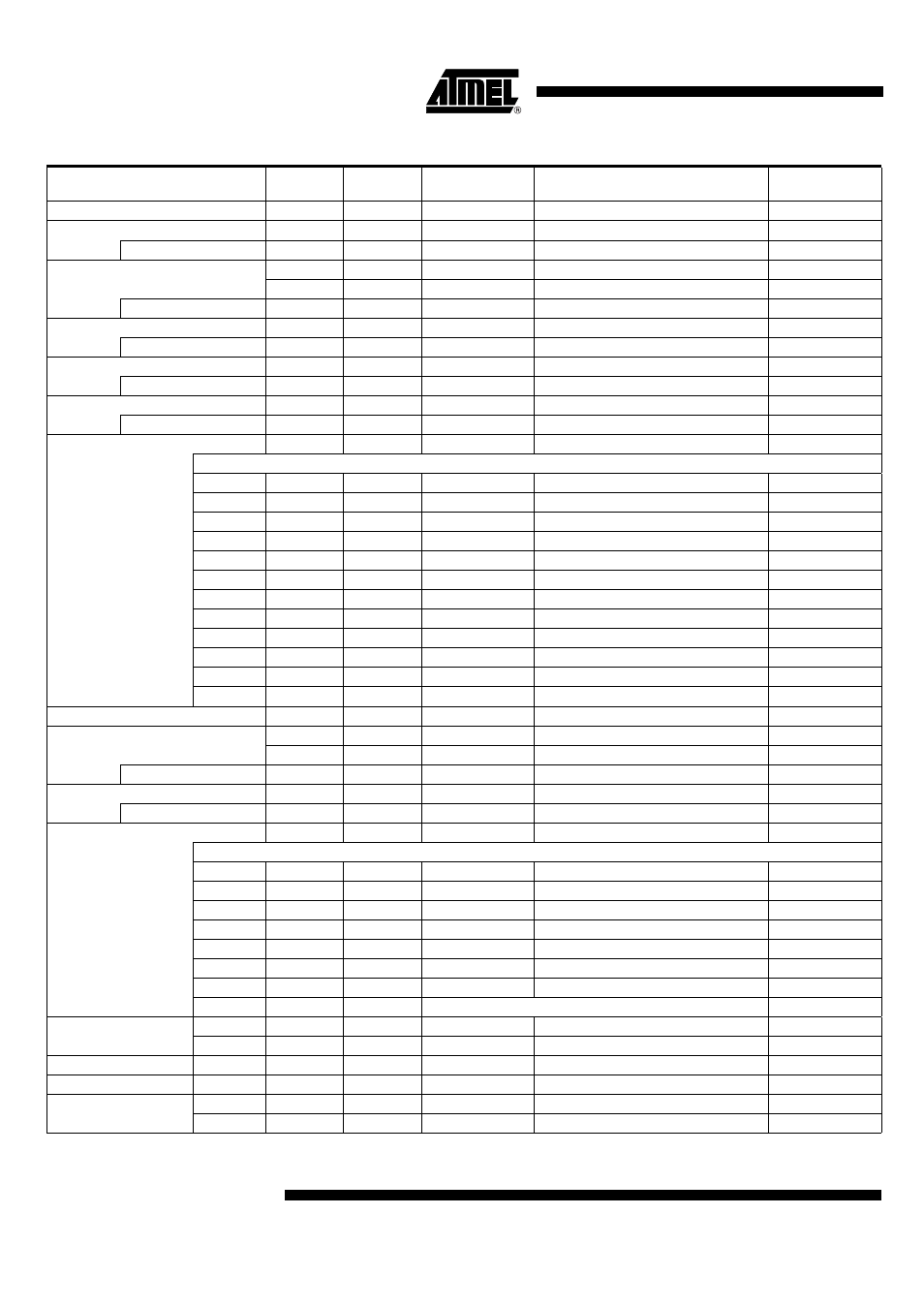
Table 6.
Peripheral Addresses
Port Address
Name
Write/
Read
Reset Value
Register Function
Module Type
1
P1DAT
W/R
1xx1b
Port 1 - data register/input data
M3
2
P2DAT
W/R
1111b
Port 2 - data register/pin data
M2
Auxiliary
P2CR
W
1111b
Port 2 - control register
M"
3
SC
W
1x11b
System configuration register
M3
CWD
R
xxxxb
Watchdog reset
M3
Auxiliary
CM
W/R
1111b
Clock management register
M2
4
P4DAT
W/R
1111b
Port 4 - data register/pin data
M2
Auxiliary
P4CR
W
1111 1111b
Port 4 - control register (byte)
M2
5
P5DAT
W/R
1111b
Port 5 - data register/pin data
M2
Auxiliary
P5CR
W
1111 1111b
Port 5 - control register (byte)
M2
6
P6DAT
W/R
1xx1b
Port 6 - data register/pin data
M2
Auxiliary
P6CR
W
1111b
Port 6 - control register (byte)
M2
7
T12SUB
W
–
Data to Timer 1/2 subport
M1
Subport address
0
T2C
W
0000b
Timer 2 control register
M1
1
T2M1
W
1111b
Timer 2 mode register 1
M1
2
T2M2
W
1111b
Timer 2 mode register 2
M1
3
T2CM
W
0000b
Timer 2 compare mode register
M1
4
T2CO1
W
1111b
Timer 2 compare register 1
M1
5
T2CO2
W
1111 1111b
Timer 2 compare register 2 (byte)
M1
6
–
–
–
Reserved
–
7
–
–
–
Reserved
–
8
T1C1
W
1111b
Timer 1 control register 1
M1
9
T1C2
W
x111b
Timer 1 control register 2
M1
A
WDC
W
1111b
Watchdog control register
M1
B-F
–
–
– Reserved
–
8
ASW
W
1111b
Auxiliary/switch register
ASW
9
STB
W
xxxx xxxxb
Serial transmit buffer (byte)
M2
SRB
R
xxxx xxxxb
Serial receive buffer (byte)
M2
Auxiliary
SIC1
W
1111b
Serial interface control register 1
M2
A
SISC
W/R
1x11b
Serial interface status/control register
M2
Auxiliary
SIC2
W
1111b
Serial interface control register 2
M2
B
T3SUB
W/R
–
Data to/from Timer 3 subport
M1
Subport address
0
T3M
W
1111b
Timer 3 mode register
M1
1
T3CS
W
1111b
Timer 3 clock select register
M1
2
T3CM1
W
0000b
Timer 3 compare mode register 1
M1
3
T3CM2
W
0000b
Timer 3 compare mode register 2
M1
4
T3CO1
W
1111 1111b
Timer 3 compare register 1 (byte)
M1
4
T3CP
R
xxxx xxxxb
Timer 3 capture register (byte)
M1
5
T3CO2
W
1111 1111b
Timer 3 compare register 2 (byte)
M1
6-F
–
–
–
Reserved
–
C
T3C
–
W
0000b
Timer 3 control register
M3
T3ST
–
R
x000b
Timer 3 status register
M3
D
–
–
–
–
Reserved
–
E
–
–
–
–
Reserved
–
F
VMC
–
W
1111b
Voltage monitor control register
M3
VMST
–
R
xx11b
Voltage monitor status register
M3