Combination mode timer 2 and timer 3, Atar862-3, Figure 86 – Rainbow Electronics ATAR862-3 User Manual
Page 84: Combination timer 2 and timer 3
84
ATAR862-3
4556B–4BMCU–02/03
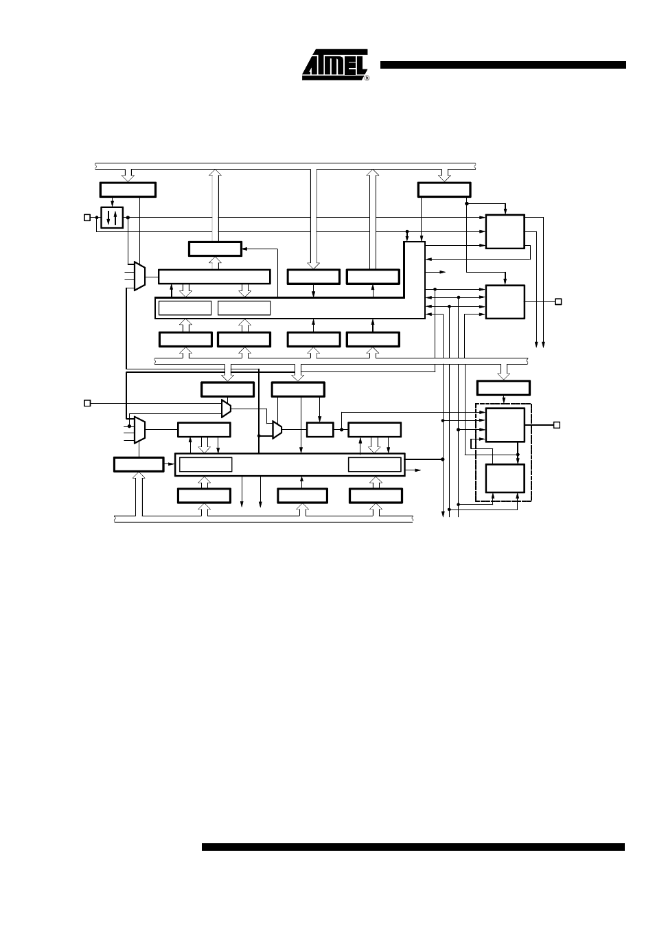
Combination Mode Timer 2 and Timer 3
Figure 86.
Combination Timer 2 and Timer 3
Combination Mode 10:
Frequency Measurement or
Event Counter with Time Gate
Timer 2 mode 1/2:
12-bit compare counter/8-bit compare counter and
4-bit prescaler
Timer 2 output mode 1/6: Timer 2 compare match toggles (TOG2) to the Timer 3
Timer 3 mode 3:
Timer/Counter; internal trigger restart and internal capture
(with Timer 2 TOG2-signal)
The counter is driven by an external (T3I) clock source. The output signal (TOG2) of
Timer 2 resets the counter. The counter value before reset is saved in the capture regis-
ter. If single-action mode is activated for one or both compare registers, the trigger
signal restarts also the single actions. This mode can be used for frequency measure-
ments or as event counter with time gate.
8-bit counter 3
RES
Compare 3/1
T3CO1
T3CP
T3CO2
Timer 3 - control
T3O
CL3
T3I
T3EX
SYSCL
T1OUT
POUT
I/O-bus
Compare 3/2
T3CM1
T3CM2
T3C
T3ST
Modulator 3
Demodu-
lator 3
Control
SO
TOG3
INT5
RES
CM31
T3I
T3EX
TOG2
SI
SCI
SSI
CP3
4-bit counter 2/1
RES
OVF1
Compare 2/1
T2CO1
CM1
POUT
SSI
CL2/2
DCG
T2M1
P4CR
8-bit counter 2/2
RES
OVF2
Compare 2/2
T2CO2
T2CM
TOG2
INT4
Biphase-,
Manchester-
modulator
OUTPUT
MOUT
M2
T2O
Timer 2
modulator 2
output-stage
T2M2
Control
(RE, FE, SCO, OMSK)
SSI
T2C
CL2/1
TOG3
SYSCL
T1OUT
SCL
Timer 2 - control
M2
T3CS
T3M
POUT
DCGO
SO
T2I
I/O-bus
I/O-bus