Frame buffer access modes (long modes) – Rainbow Electronics AT86RF230 User Manual
Page 27
27
AT86RF230
5131A-ZIGB-06/14/06
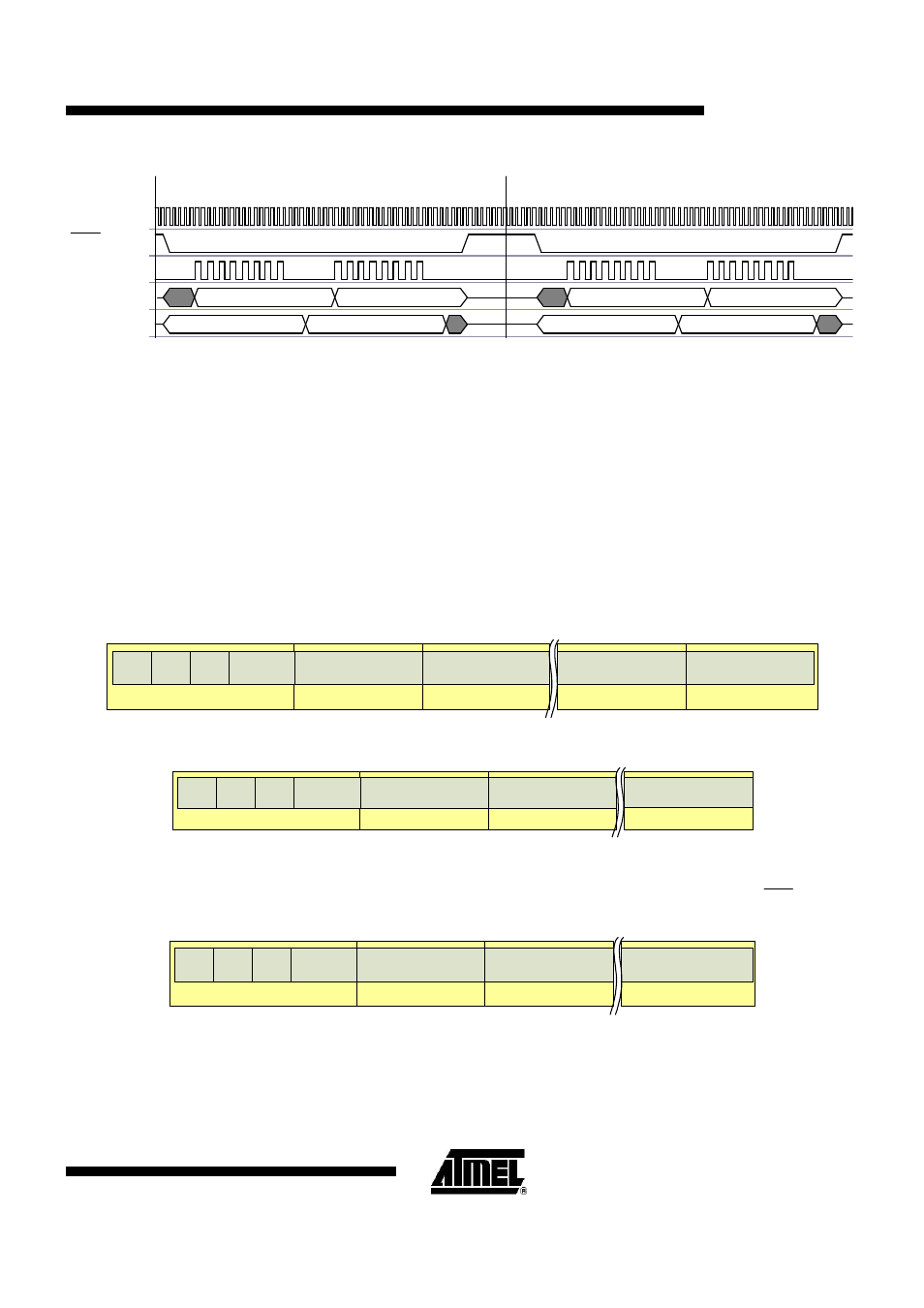
CLKM
SEL
SCLK
MOSI
MISO
COMMAND
WRITE DATA
COMMAND
XX
XX
XX
XX
READ DATA
Write Register Access
Read Register Access
Figure 7-4.
SPI Register Access Sequence
7.3. Frame Buffer Access Modes (Long Modes)
These modes are used to upload or download frames as well as access the frame buffer directly. Each transfer
starts with a control byte. If this byte indicates a frame upload or download, the next byte indicates the frame length
followed by the PSDU data. In receive mode, after the PSDU data has been received, one more byte is attached,
containing LQI information.
The number of bytes for one frame access must be calculated by the controller as follows:
Transmit:
byte_count = command byte + frame length byte + frame length
Receive:
byte_count = command byte + frame length byte + frame length + LQI byte
That means there is a maximum frame buffer access of 129 bytes for TX and 130 bytes for RX.
byte 3
byte n
byte n-1
byte 2
byte 1
control[4:0]
(reserved)
frame_length[7:0]
TX/RX
0
0
data[7:0]
data[7:0]
1
LQI[7:0]
Figure 7-5.
Frame Receive Mode
byte 3
byte n
byte 2
byte 1
control[4:0]
(reserved)
frame_length[7:0]
TX/RX
1
0
data[7:0]
data[7:0]
1
Figure 7-6.
Frame Transmit Mode
If the control byte indicates SRAM access mode, the next byte contains the start address. As long as
SEL
is low,
every subsequent byte read or write increments the address counter of the frame buffer.
byte 1
byte 2
byte 3
byte n
control[4:0]
(reserved)
address[7:0]
R/W
1=write
0=read
0
data[7:0]
data[7:0]
0
Figure 7-7.
SRAM Access Mode