Phy to micro-controller interface, Spi protocol – Rainbow Electronics AT86RF230 User Manual
Page 25
25
AT86RF230
5131A-ZIGB-06/14/06
7. PHY to Micro-Controller Interface
In the following paragraphs, the PHY to micro-controller interface is defined. The SPI protocol and timing access
are shown, as well as buffer access modes with examples.
Controllers with an SPI interface such as an AVR will work with the AT86RF230 interface. The SPI interface is
used for both register programming as well as for frame transfer. The additional control signals are connected to
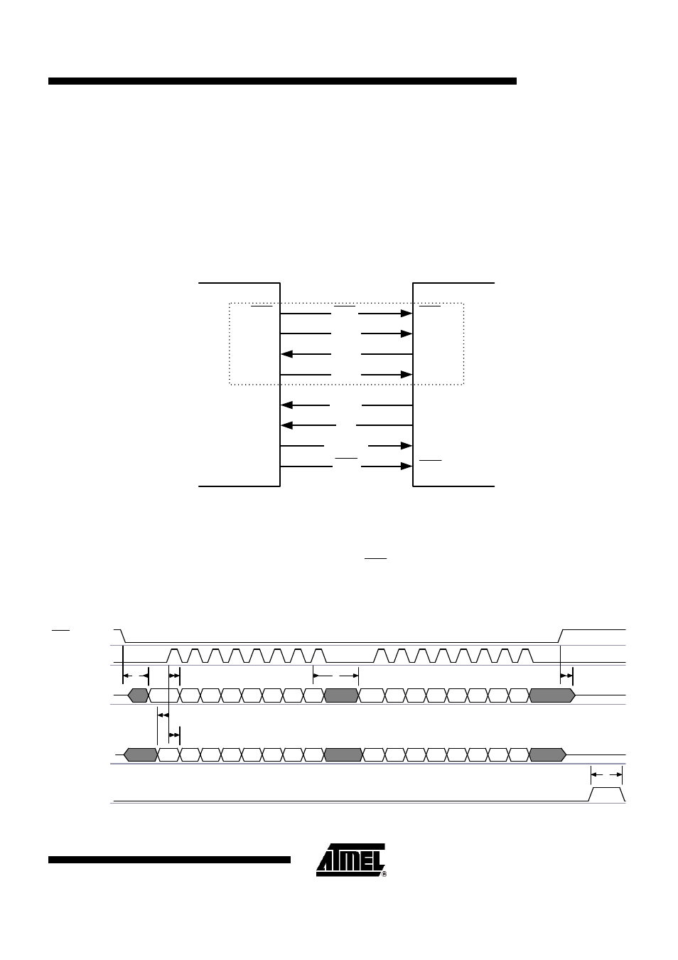
the GPIO interface of the controller. Figure 7-1 shows the signals which need to be connected between the
controller and the transceiver. The CLKM signal can be used as a controller main clock (synchronous mode) or as
software timer reference (asynchronous mode).
Micro-Controller
AT86RF230
MOSI
MISO
SCLK
CLKM
IRQ
SLP_TR
MOSI
MISO
SCLK
GPIO1/CLK
GPIO2/IRQ
GPIO3
MOSI
MISO
SCLK
CLKM
IRQ
SLP_TR
GPIO4
S
P
I
SEL
SEL
SEL
RST
RST
Figure 7-1.
PHY-HOST Interface
7.1. SPI Protocol
SPI is used to program control registers as well as to transfer data frames between the controller and the
AT86RF230. The additional signals CLKM, IRQ, SLP_TR and
RST
are connected to the GPIO interface of the
controller.
The internal 128-byte frame buffer can keep one TX or one RX frame of maximum length at a time. This offers a
very flexible data rate over the SPI interface.
SEL
SCLK
MISO
MOSI
SLP_TR
Bit7
Bit6 Bit5 Bit4 Bit3 Bit2 Bit1 Bit0
Bit7
Bit6 Bit5 Bit4 Bit3 Bit2 Bit1 Bit0
Bit7 Bit6 Bit5 Bit4 Bit3 Bit2 Bit1 Bit0
Bit7 Bit6 Bit5 Bit4 Bit3 Bit2 Bit1 Bit0
t7
t4
t2
t1
t5
t6
t3
Figure 7-2.
SPI Timing