Pll frequency synthesizer – Rainbow Electronics AT86RF230 User Manual
Page 23
23
AT86RF230
5131A-ZIGB-06/14/06
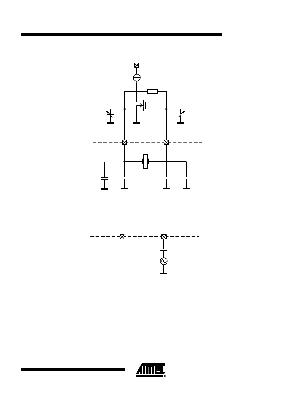
CX
CX
16MHz
XTAL1
XTAL2
VDD
C
TRIM
C
TRIM
C
PAR
C
PAR
AT86RF230
PCB
XTAL_TRIM[3:0]
XTAL_TRIM[3:0]
Figure 6-3.
Simplified XOSC Schematic with External Components
When using an external reference frequency, the signal needs to be connected to pin XTAL1 as indicated in Figure
6-4 and the register bits XTAL_MODE needs to be set to the external oscillator mode. The oscillation amplitude
shouldn’t be larger than 500 mV, peak-to-peak.
XTAL1
XTAL2
AT86RF230
PCB
16 MHz
Figure 6-4.
Setup for Using an External Frequency Reference
6.7. PLL Frequency Synthesizer
The synthesizer of the AT86RF230 is implemented as a fractional-N PLL. Two calibration loops ensure correct
functionality within the specified operating limits.
The center frequency control loop ensures a correct center frequency of the VCO for the currently programmed
channel. The center frequency calibration algorithm can be started manually by setting PLL_CF_START = 1 of
register 0x1A (PLL_CF). The result of the calibration is also available in this register.
The delay calibration unit compensates the phase errors inherent in fractional-N PLLs. Using this technique,
unwanted spurious frequency components beside the RF carrier are suppressed, and the PLL behaves almost like
an integer-N PLL. A calibration cycle can be initiated by setting the register bit PLL_DCU_START = 1 of the
register 0x1B (PLL_DCU). The calibration result is written to the register bits PLL_DCUW.