Wire serial interface and data description – Rainbow Electronics AT84AD004 User Manual
Page 35
35
AT84AD004
5390A–BDC–06/04
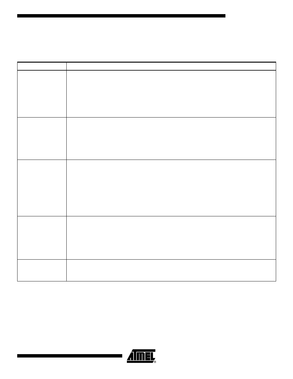
3-wire Serial Interface and
Data Description
The 3-wire bus is activated with the control bit mode set to 1. The length of the word is
19 bits: 16 for the data and 3 for the address. The maximum clock frequency is
50 MHz.
Table 10. 3-wire Serial Interface Address Setting Description
Address
Setting
000
Standby
Gray/binary mode
1:1 or 1:2 DMUX mode
Analog input MUX
Clock selection
Auto-calibration
Decimation test mode
Data Ready Delay Adjust
001
Analog gain adjustment
Data7 to Data0: gain channel I
Data15 to Data8: gain channel Q
Code 00000000: -1.5 dB
Code 10000000: 0 dB
Code 11111111: 1.5 dB
Steps: 0.011 dB
010
Offset compensation
Data7 to Data0: offset channel I
Data15 to Data8: offset channel Q
Data7 and Data15: sign bits
Code 11111111b: 31.75 LSB
Code 10000000b: 0 LSB
Code 00000000b: 0 LSB
Code 01111111b: -31.75 LSB
Steps: 0.25 LSB
Maximum correction: ±31.75 LSB
011
Gain compensation
Data6 to Data0: channel I/Q (Q is matched to I)
Code 11111111b: -0.315 dB
Code 10000000b: 0 dB
Code 0000000b: 0 dB
Code 0111111b: 0.315 dB
Steps: 0.005 dB
Data6: sign bit
100
Internal Settling Adjustment (ISA)
Data2 to Data0: channel I
Data5 to Data3: channel Q
Data15 to Data6: 1000010000