Ata6824 [preliminary – Rainbow Electronics ATA6824 User Manual
Page 9
9
4931C–AUTO–09/06
ATA6824 [Preliminary]
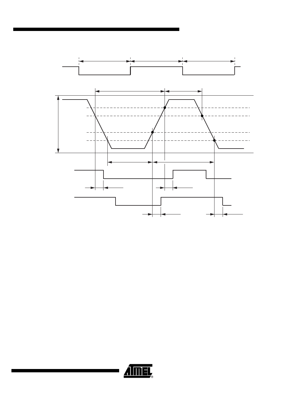
Figure 5-3.
Definition of Bus Timing Parameters
The recessive BUS level is generated from the integrated 30 k
Ω
pull-up resistor in series with an
active diode. This diode prevents the reverse current of VBUS during differential voltage
between VSUP and BUS (V
BUS
> V
SUP
).
t
Bit
TH
Rec(min)
TH
Dom(min)
TH
Rec(max)
Thresholds of
receiving node 2
Thresholds of
receiving node 1
TH
Dom(max)
t
Bus_dom(max)
t
Bus_rec(min)
t
Bus_dom(min)
t
rx_pdr(2)
t
rx_pdf(2)
t
rx_pdf(1)
t
rx_pdr(1)
t
Bus_rec(max)
t
Bit
t
Bit
V
S
(Transceiver
supply
of transmitting
node)
RXD
(output of receiving Node 2)
RXD
(output of receiving Node 1)
TXD
SIO Bus Signal
(input to transmitting Node)
See also other documents in the category Rainbow Electronics Software:
- MAX14514 (14 pages)
- MAX16825 (15 pages)
- MAX16800 (9 pages)
- MAX6931 (14 pages)
- MAX6920 (10 pages)
- MAX6959 (19 pages)
- MAX15025 (16 pages)
- EVK2 (2 pages)
- MAX13256 (17 pages)
- MAX6964 (23 pages)
- MAX6948B (28 pages)
- MAX17117 (22 pages)
- MAX6934 (16 pages)
- MAX5048 (9 pages)
- MAX15054 (9 pages)
- AT6010LV (28 pages)
- AT83C24NDS (42 pages)
- AT83C21GC (6 pages)
- AT42QT1012 (6 pages)
- ATF16LV8C (11 pages)
- ATA6823 (28 pages)
- 71M6542G (165 pages)
- ATV2500BQL (21 pages)
- ATV750BL (19 pages)
- ATA6839 (17 pages)
- BA6229 (3 pages)
- ATF16V8C (18 pages)
- ATMOS™ 1M60 (26 pages)
- ATF1504ASVL (29 pages)
- BA6955N (9 pages)
- ATF1500ABV (15 pages)
- BA6219BFP-Y (7 pages)
- AT77C102B (19 pages)
- AT90SCR050 (4 pages)
- BA6208F (2 pages)
- ATA6625 (22 pages)
- ATA6664 (20 pages)
- ATF1516ASL (13 pages)
- ATF20V8BQL (18 pages)
- ATA6827 (15 pages)
- AT83C26 (77 pages)
- AT77C104B (36 pages)
- ATA6830 (23 pages)
- AT42QT1040 (18 pages)