Ata6824 [preliminary – Rainbow Electronics ATA6824 User Manual
Page 7
7
4931C–AUTO–09/06
ATA6824 [Preliminary]
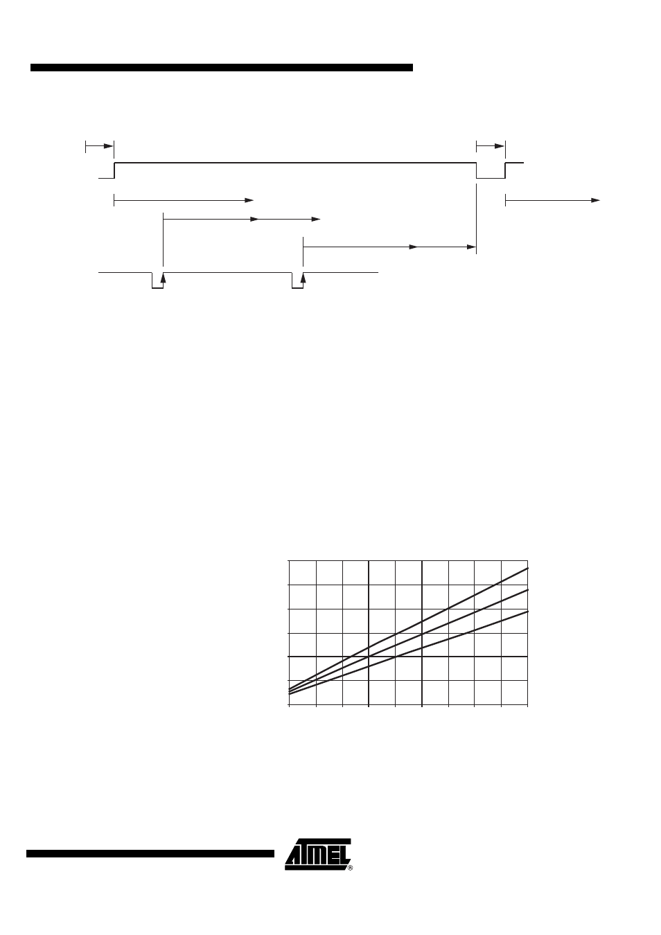
Figure 5-1.
Timing Diagram of the Watchdog Function
5.3.1
Timing Sequence
For example, with an external resistor R
WD
= 33 k
Ω
±1% we get the following typical parameters
of the watchdog.
T
OSC
= 12.32 µs, t
1
= 12.1 ms, t
2
= 9.61 ms, T
WD
= 16.88 ms ±10%
The times t
res
= 68 ms and t
d
= 68 ms are fixed values with a tolerance of 10%.
After ramp-up of the battery voltage (power-on reset), the V
CC
regulator is switched on. The
reset output, /RESET, stays low for the time t
res
(typically 68 ms), then switches to high. For an
initial lead time t
d
(typically 68 ms for setups in the controller) the watchdog waits for a rising
edge on WD to start its normal window watchdog sequence. If no rising edge is detected, the
watchdog will reset the microcontroller for t
res
and wait t
d
for the rising edge on WD.
Times t
1
(close window) and t
2
(open window) form the window watchdog sequence. To avoid
receiving a reset from the watchdog, the triggering signal from the microcontroller must hit the
timeframe of t
2
= 9.61 ms. The trigger event will restart the watchdog sequence.
Figure 5-2.
T
WD
versus R
WD
t
2
t
1
t
2
t
1
t
d
t
d
t
resshort
t
res
WD
/RESET
RWD (k
Ω
)
TWD (ms)
max
min
0
10
20
30
40
50
60
10
20
30
40
50
60
70
80
90
100
typ