4 ac characteristics – maximum clock frequencies, 5 ac characteristics – all other parameters, 4 ac characteristics – Rainbow Electronics AT25DQ321 User Manual
Page 55
55
AT25DQ321 [DATASHEET]
8718D–DFLASH–12/2012
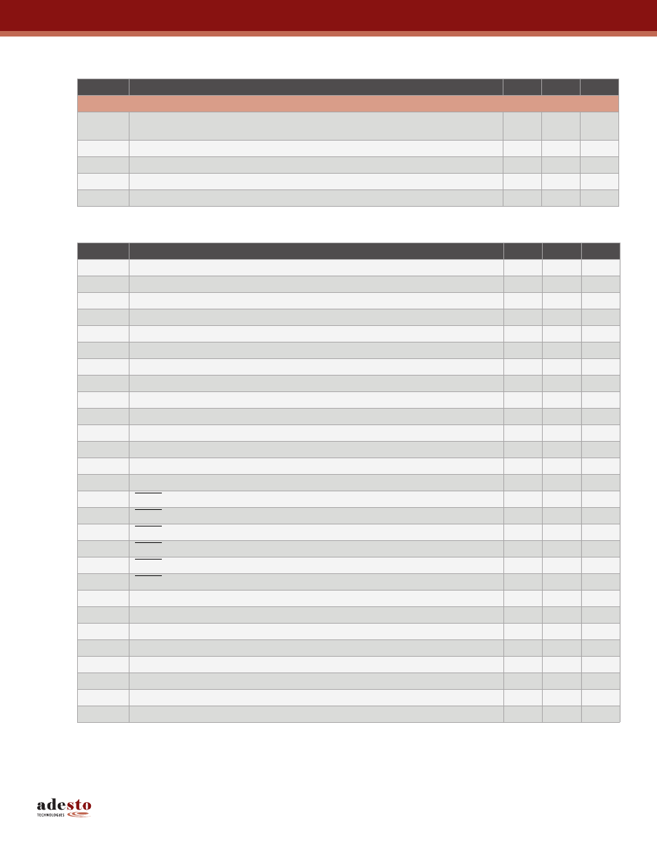
13.4 AC Characteristics
–
Maximum Clock Frequencies
13.5 AC Characteristics – All Other Parameters
Notes: 1. Not 100% tested. (Value guaranteed by design and characterization)
2. 15pF load at frequencies above 70MHz, 30pF otherwise.
3. Only applicable as a constraint for the Write Status Register Byte 1 command when SPRL = 1.
Symbol
Parameter
Min
Max
Units
RapidS and SPI Operation
f
MAX
Maximum Clock Frequency for All Operations – RapidS Operation Only
(Excluding 03h, 0Bh, 3Bh, 6Bh, and 9F Opcodes)
100
MHz
f
CLK
Maximum Clock Frequency for All Operations (Excluding 03h Opcode)
85
MHz
f
RDLF
Maximum Clock Frequency for 03h Opcode (Read Array – Low Frequency)
50
MHz
f
RDDO
Maximum Clock Frequency for 3Bh Opcode (Dual-Output Read)
85
MHz
f
RDQO
Maximum Clock Frequency for 6Bh Opcode (Quad-Output Read)
66
MHz
Symbol
Parameter
Min
Max
Units
t
CLKH
Clock High Time
4.3
ns
t
CLKL
Clock Low Time
4.3
ns
t
Clock Rise Time, Peak-to-Peak (Slew Rate)
0.1
V/ns
t
CLKF
Clock Fall Time, Peak-to-Peak (Slew Rate)
0.1
V/ns
t
CSH
Chip Select High Time
50
ns
t
CSLS
Chip Select Low Setup Time (Relative to Clock)
5
ns
t
CSLH
Chip Select Low Hold Time (Relative to Clock)
5
ns
t
CSHS
Chip Select High Setup Time (Relative to Clock)
5
ns
t
CSHH
Chip Select High Hold Time (Relative to Clock)
5
ns
t
DS
Data In Setup Time
2
ns
t
DH
Data In Hold Time
1
ns
t
DIS
Output Disable Time
5
ns
t
Output Valid Time
5
ns
t
OH
Output Hold Time
2
ns
t
HLS
HOLD Low Setup Time (Relative to Clock)
5
ns
t
HLH
HOLD Low Hold Time (Relative to Clock)
5
ns
t
HHS
HOLD High Setup Time (Relative to Clock)
5
ns
t
HHH
HOLD High Hold Time (Relative to Clock)
5
ns
t
HOLD Low to Output High-Z
5
ns
t
HHQX
HOLD High to Output Low-Z
5
ns
t
WPS
Write Protect Setup Time
20
ns
t
Write Protect Hold Time
100
ns
t
SECP
Sector Protect Time (From Chip Select High)
20
ns
t
Sector Unprotect Time (From Chip Select High)
20
ns
t
LOCK
Sector Lockdown and Freeze Sector Lockdown State Time (From Chip Select High)
200
μs
t
EDPD
Chip Select High to Deep Power-Down
1
μs
t
Chip Select High to Standby Mode
30
μs
t
RST
Reset Time
30
μs