3 waveform 3 – rapids mode 0 (fmax = 66mhz), 4 waveform 4 – rapids mode 3 (fmax = 66mhz), 5 utilizing the rapids function – Rainbow Electronics AT45DB161D User Manual
Page 33
33
3500O–DFLASH–11/2012
AT45DB161D
21.2
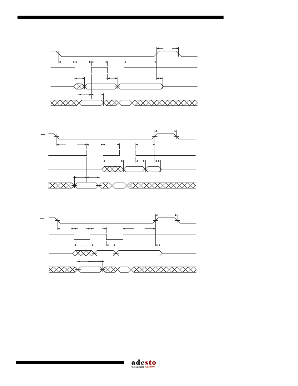
Waveform 2 – SPI Mode 3 Compatible (for frequencies up to 66MHz)
21.3
Waveform 3 – RapidS Mode 0 (F
MAX
= 66MHz)
21.4
Waveform 4 – RapidS Mode 3 (F
MAX
= 66MHz)
21.5
Utilizing the RapidS Function
To take advantage of the RapidS function's ability to operate at higher clock frequencies, a full clock cycle must be
used to transmit data back and forth across the serial bus. The DataFlash is designed to always clock its data out
on the falling edge of the SCK signal and clock data in on the rising edge of SCK.
For full clock cycle operation to be achieved, when the DataFlash is clocking data out on the falling edge of SCK,
the host controller should wait until the next falling edge of SCK to latch the data in. Similarly, the host controller
should clock its data out on the rising edge of SCK in order to give the DataFlash a full clock cycle to latch the
incoming data in on the next rising edge of SCK.
CS
SCK
SO
t
CSS
VALID IN
t
H
t
SU
t
WL
t
WH
t
CSH
t
CS
t
V
HIGH Z
VALID OUT
t
HO
t
DIS
HIGH IMPEDANCE
SI
CS
SCK
SI
SO
t
CSS
VALID IN
t
H
t
SU
t
WH
t
WL
t
CSH
t
CS
t
V
HIGH IMPEDANCE
VALID OUT
t
HO
t
DIS
HIGH IMPEDANCE
CS
SCK
SO
t
CSS
VALID IN
t
H
t
SU
t
WL
t
WH
t
CSH
t
CS
t
V
HIGH Z
VALID OUT
t
HO
t
DIS
HIGH IMPEDANCE
SI