Rainbow Electronics AT45DB011B User Manual
Page 11
11
AT45DB011B
1984E–DFLSH–10/02
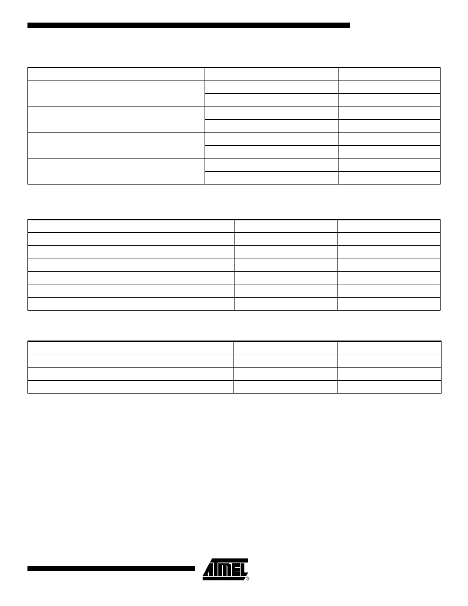
Note:
In Tables 2 and 3, an SCK mode designation of “Any” denotes any one of the four modes of operation (Inactive Clock Polarity
Low, Inactive Clock Polarity High, SPI Mode 0, or SPI Mode 3).
Table 1. Read Commands
Command
SCK Mode
Opcode
Continuous Array Read
Inactive Clock Polarity Low or High
68H
SPI Mode 0 or 3
E8H
Main Memory Page Read
Inactive Clock Polarity Low or High
52H
SPI Mode 0 or 3
D2H
Buffer Read
Inactive Clock Polarity Low or High
54H
SPI Mode 0 or 3
D4H
Status Register Read
Inactive Clock Polarity Low or High
57H
SPI Mode 0 or 3
D7H
Table 2. Program and Erase Commands
Command
SCK Mode
Opcode
Buffer Write
Any
84H
Buffer to Main Memory Page Program with Built-in Erase
Any
83H
Buffer to Main Memory Page Program without Built-in Erase
Any
88H
Page Erase
Any
81H
Block Erase
Any
50H
Main Memory Page Program through Buffer
Any
82H
Table 3. Additional Commands
Command
SCK Mode
Opcode
Main Memory Page to Buffer Transfer
Any
53H
Main Memory Page to Buffer Compare
Any
60H
Auto Page Rewrite through Buffer
Any
58H