Crystal selection guidelines, Rf12b, Recommended packet structures – Rainbow Electronics RF12B User Manual
Page 26
RF12B
Tel: +86-755-86096587 Fax: +86-755-86096602 E-mail: [email protected] http://www.hoperf.com
Polling Mode:
When nFFS signal is low the FIFO output is connected directly to the SDO pin and its content can be
clocked out by the SCK. Set the FIFO IT level to 1. In this case, as long as FFIT indicates received bits in
the FIFO, the controller may continue to take the bits away. When FFIT goes low, no more bits need to be
taken. An SPI read command is also available to read out the content of the FIFO.
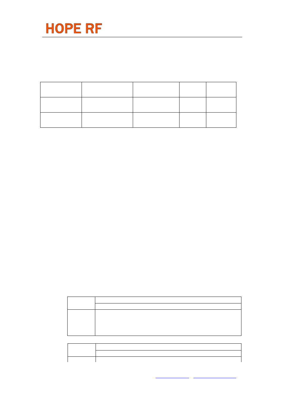
RECOMMENDED PACKET STRUCTURES
Preamble
Synchron word
(Can be network ID)
Payload
CRC
Minimum length
4 - 8 bit (1010b or 0101b)
D4h (programmable)
?
4 bit - 1 byte
Recommended
length
8 -12 bit (e.g. AAh or 55h)
2DD4h (D4 is
programmable)
?
2 byte
CRYSTAL SELECTION GUIDELINES
The crystal oscillator of the RF12B requires a 10 MHz parallel mode crystal. The circuit contains an
integrated load capacitor in order to minimize the external component count. The internal load
capacitance value is programmable from 8.5 pF to 16 pF in 0.5pF steps. With appropriate PCB layout,
the total load capacitance value can be 10 pF to 20 pF so a variety of crystal types can be used.
When the total load capacitance is not more than 20 pF and a worst case 7 pF shunt capacitance (C
0
)
value is expected for the crystal, the oscillator is able to start up with any crystal having less than 300
ohms ESR (equivalent series loss resistance). However, lower C
0
and ESR values guarantee faster
oscillator startup.
The crystal frequency is used as the reference of the PLL, which generates the local oscillator
frequency (f
LO
). Therefore f
LO
is directly proportional to the crystal frequency. The accuracy requirements
for production tolerance, temperature drift and aging can thus be determined from the maximum
allowable local oscillator frequency error.
Whenever a low frequency error is essential for the application, it is possible to “pull” the crystal to
the accurate frequency by changing the load capacitor value. The widest pulling range can be achieved if
the nominal required load capacitance of the crystal is in the “midrange”, for example 16 pF. The
“pull-ability” of the crystal is defined by its motional capacitance and C
0
.
Maximum XTAL Tolerances Including Temperature and Aging [ppm]
Bit Rate:
2.4 kbps
Deviation [+/- kHz]
30 45
60
75
90
105
120
315
MHz 25 50
75
100
100
100
100
433
MHz 20 30
50
70
90
100
100
868
MHz 10 20
25
30
40
50
60
915
MHz 10 15
25
30
40
50
50
Bit Rate:
9.6 kbps
Deviation [+/- kHz]
30 45
60
75
90
105
120
315
MHz 20 50
70
75
100
100
100