Rf12b – Rainbow Electronics RF12B User Manual
Page 20
RF12B
only one transmitter. After a complete measuring cycle, the measured value is kept independently of the
state of the VDI signal.
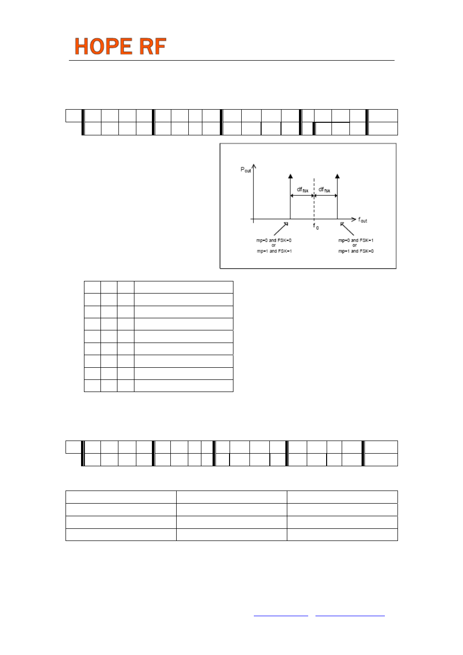
11. TX Configuration Control Command
bit 15 14 13 12 11 10 9
8 7 6 5 4 3
2 1 0 POR
1 0 0 1 1 0 0
mp
m3
m2
m1
m0
0
p2
p1 p0 9800h
Bits 8-4 (mp, m3 to m0):FSK modulation
parameters:
The resulting output frequency can be
calculated as:
Tel: +86-755-86096587 Fax: +86-755-86096602 E-mail: [email protected] http://www.hoperf.com
f
out
= f + (-1)
SIGN
* (M + 1) * (15 kHz)
0
Where:
f0
is the channel center frequency (see the
Frequency Setting Command
)
M
is the four bit binary number
SIGN = (mp) XOR (Data bit)
Bits 2-0 (p2 to p0): Output power:
p2 p1 p0 Relative Output Power [dB]
0 0 0 0
0 0 1 -3
0 1 0 -6
0 1 1 -9
1 0 0 -12
1 0 1 -15
1 1 0 -18
1 1 1 -21
The output power given in the table is relative to the maximum available power, which depends on the
actual antenna impedance.
12. PLL Setting Command
bit 15 14 13 12 11 10 9
8
7 6 5 4 3 2 1 0 POR
1 1 0 0 1 1 0
0
0
ob1
ob0
lpx
ddy
ddit
1 bw0
CC67h
Note:
POR default setting of the register carefully selected to cover almost all typical applications.
Bit 6-5 (ob1-ob0): Microcontroller output clock buffer rise and fall time control.
ob1
ob0
Selected uC CLK frequency
0
0
5 or 10 MHz (recommended)
0
1
3.3 MHz
1
X
2.5 MHz or less
Note:
Needed for optimization of the RF performace. Optimal settings can vary by the actual external
parasitic capacitances.