Rf12b – Rainbow Electronics RF12B User Manual
Page 19
RF12B
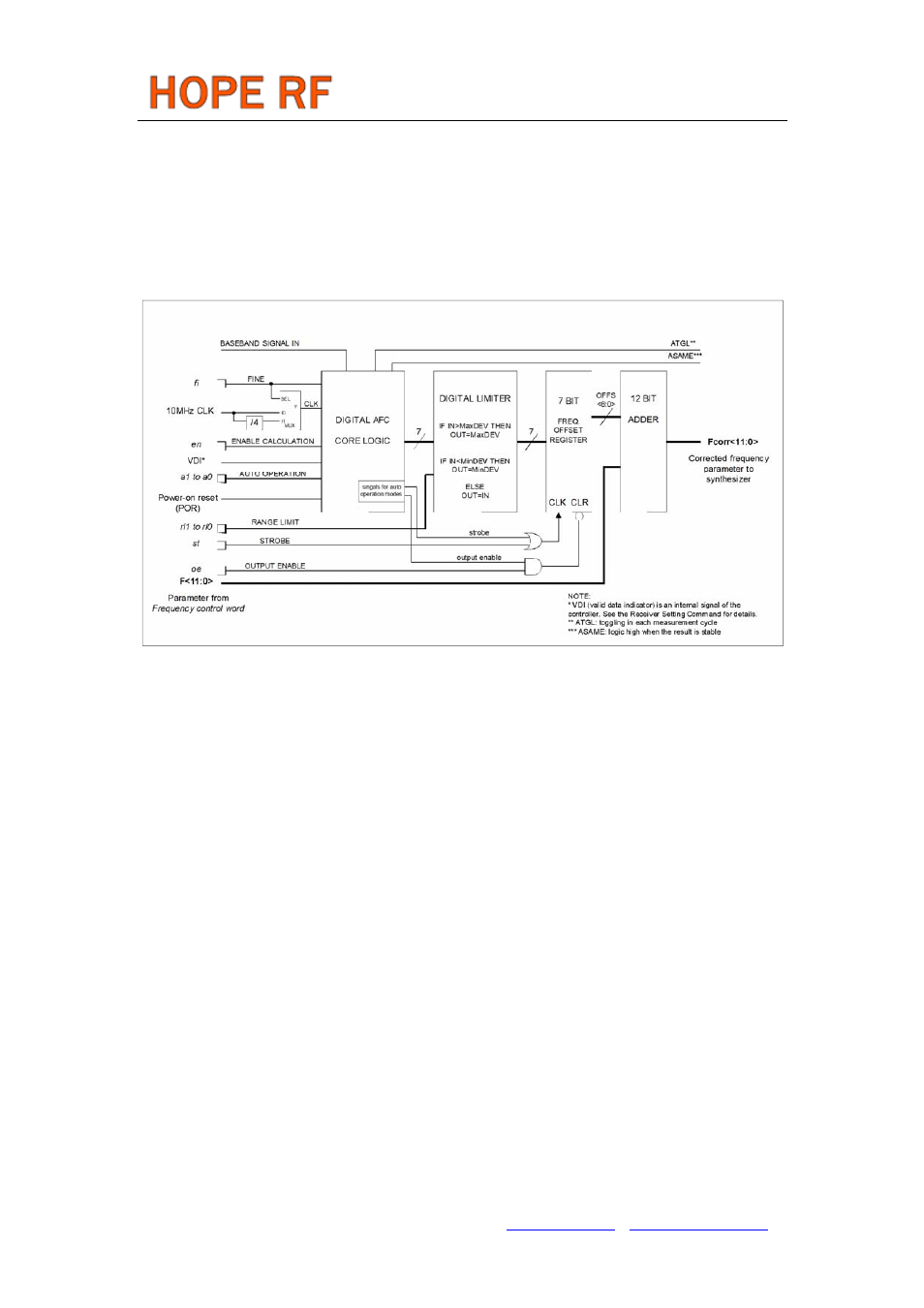
Bit 3 (st): Strobe edge, when st goes to high, the actual latest calculated frequency error is stored into the
offset register of the AFC block.
Bit 2 (fi): Switches the circuit to high accuracy (fine) mode. In this case, the processing time is about twice
longer, but the measurement uncertainty is about the half.
Bit 1 (oe): Enables the frequency offset register. It allows the addition of the offset register to the
frequency control word of the PLL.
Bit 0 (en): Enables the calculation of the offset frequency by the AFC circuit.
Note
: Lock bit is high when the AFC loop is locked, f_same bit indicates when two subsequent measuring
results are the same, toggle bit changes state in every measurement cycle.
In automatic operation mode (no strobe signal is needed from the microcontroller to update the
output offset register) the AFC circuit is automatically enabled when the VDI indicates potential incoming
signal during the whole measurement cycle and the circuit measures the same result in two subsequent
cycles.
There are three operation modes, examples from the possible application:
1
, (a1=0, a0=1) the circuit measures the frequency offset only once after power up. This way, extended
TX-RX maximum distance can be achieved.
Possible application:
In the final application, when the user inserts the battery, the circuit measures and compensates for
the frequency offset caused by the crystal tolerances. This method allows for the use of a cheaper quartz
in the application and provides protection against tracking an interferer.
2a
, (a1=1, a0=0) the circuit automatically measures the frequency offset during an initial effective low
data rate pattern –easier to receive- (i.e.: 00110011) of the package and changes the receiving frequency
accordingly. The further part of the package can be received by the corrected frequency settings.
2b
, (a1=1, a0=0) the transmitter must transmit the first part of the packet with a step higher deviation and
later there is a possibility of reducing it.
In both cases (2a and 2b), when the VDI indicates poor receiving conditions (VDI goes low), the
output register is automatically cleared. Use these settings when receiving signals from different
transmitters transmitting in the same nominal frequencies.
3
, (a1=1, a0=1) It’s the same as 2a and 2b modes, but suggested to use when a receiver operates with
Tel: +86-755-86096587 Fax: +86-755-86096602 E-mail: [email protected] http://www.hoperf.com