Rc1180-mbus – Rainbow Electronics RC1180-MBUS User Manual
Page 7
RC1180-MBUS
2008 Radiocrafts AS
RC1180-MBUS Data Sheet (rev. 1.0)
Page 7 of 28
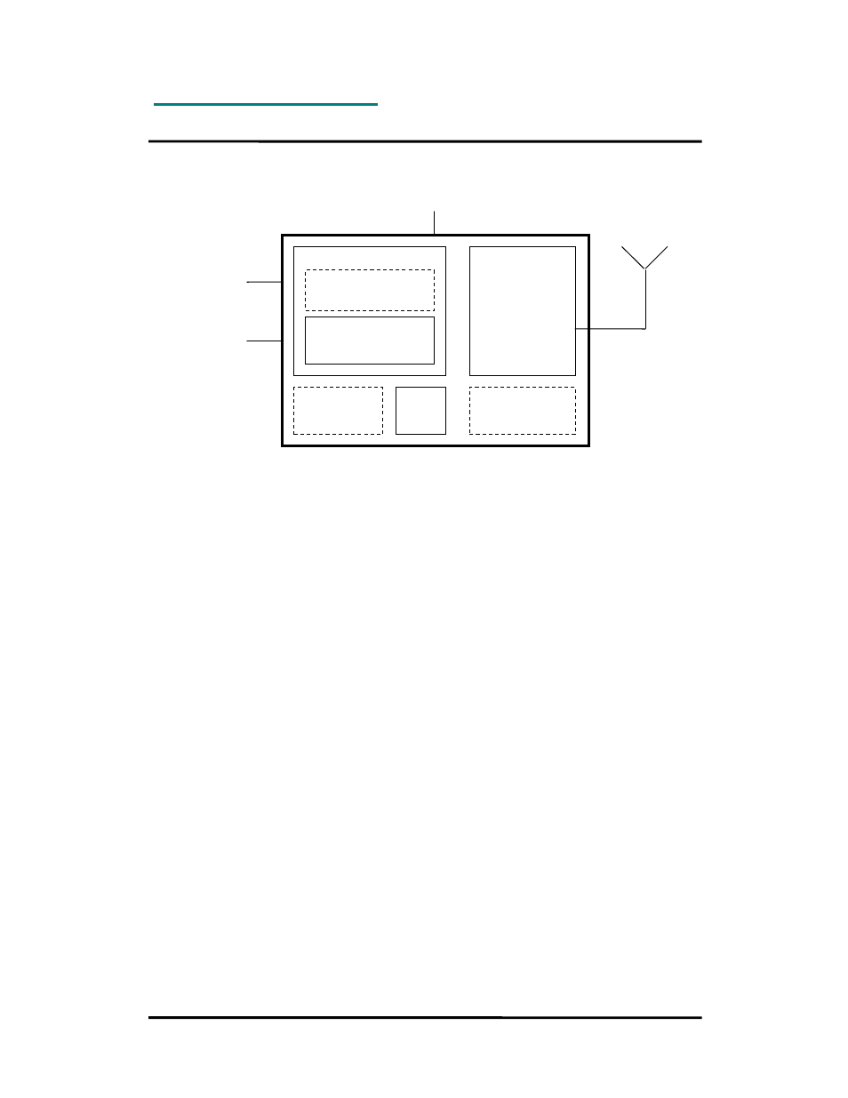
Block Diagram
Circuit Description
The module contains a communication controller with embedded Wireless M-Bus protocol
software and a high performance RF transceiver. As an option the module can support a real
time clock oscillator and EEPROM memory.
The communication controller handles the radio packet protocol, the UART interface and
controls the RF transceiver. Data to be sent by the host is received at the RXD pin and
buffered in the communication controller. The data packet is then assembled with preamble,
start-of-frame delimited (SOF), manufacturer ID, unique address information and CRC check
sums before it is transmitted on RF.
The RF transceiver modulates the data to be transmitted on RF frequency, and demodulates
data that are received. Digital signal processing technology is used to enhance sensitivity and
selectivity.
Received data are checked for correct CRC by the communication controller. If no CRC
errors were detected, the data packet is sent to the host on the TXD line. The data format is
configurable, and optionally an RSSI value (signal strength of received packet) can be added
to the message.
The asynchronous UART interface consists of RXD and TXD. Optionally CTS or RTS can be
used for hardware handshake flow control.
When a 00h value is sent as the first byte (replacing the Length byte), or the CONFIG pin is
asserted, the module enters configuration mode and the communication controller interprets
data received on the RXD pin as configuration commands. There are commands to change
the radio channel, the output power, etc. Permanent changes of the configuration is also
possible and are then stored in internal non-volatile memory (Flash).
The supply voltage is connected to the VCC pin. The module contains an internal voltage
regulator for the RF transceiver and can therefore operate over a wide supply voltage range.
Wireless M-Bus
protocol
Wireless M-Bus
RF Tranceiver
8-bit MCU
M-Bus Application
(option)
UART interface
2.0 - 3.6 V
4kB EEPROM
(option)
32 kHz
Real Time Clock
(option)
32 MHz
clock
Pulse input (option)