Rc1180-mbus – Rainbow Electronics RC1180-MBUS User Manual
Page 2
RC1180-MBUS
2008 Radiocrafts AS
RC1180-MBUS Data Sheet (rev. 1.0)
Page 2 of 28
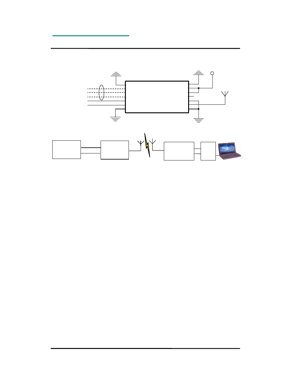
Typical application circuit
GND
CTS
RTS
CONFIG
TXD
RXD
GND
GND
VCC
RESET_N
NC
GND
RF
GND
2.0 – 3.6 V
Antenna
{
To host meter or
RS232/422/485
driver
NC
Optional
Quick Product Introduction
How do I transmit data?
Send your data to the RXD pin on the module. Use the UART format with settings (19200, 8,
1, N, no flow control). Up to 128 bytes are buffered in the module. The first byte of the
message should contain the message length. The module will transmit the data when the
whole packet is received.
How do I receive data?
Any received data packet with correct M-Bus format and check sums will be sent on the TXD
pin. Optionally the meter address (first M-Bus block) is added to the data string. The RSSI
value (received signal strength) can optionally be added to the message.
What about the antenna?
In most cases a simple quarter wavelength wire or a PCB track will do. Connect a piece of
wire to the RF pin with length corresponding to the quarter of a wavelength. For space limited
products, contact Radiocrafts and we will recommend the best antenna solution for your
application.
How do I change the M-Bus mode, RF channel or any other parameter?
To change configurable parameters, send one byte to the module with the value 0x00. This
will take the module into configuration mode. Special commands are then used to access the
configuration registers and test modes. Exit from configuration mode by sending the ‘X’
command. Parameters can be changed permanently and stored in non-volatile memory in the
module.
Meter
RC1180-MBUS
(modem)
RC1180-MBUS
(modem)
UART to:
RS232
RS485
USB
Ethernet
UART
RXD
TXD