Electrical characteristics (continued) – Rainbow Electronics MAX5971B User Manual
Page 6
6 ______________________________________________________________________________________
MAX5971B
Single-Port, 40W, IEEE 802.3af/at,
PSE Controller with I
2
C
Note 2: This device is production tested at T
A
= +25°C. Limits to T
A
=
-40°C to +85°C are guaranteed by design.
Note 3: Default thresholds are set by the classification result in auto mode. The thresholds are manually software programmable
through the ICUT Register (R2Ah[2:0]). If ILIM1 and ILIM2 are both unconnected, Class 5 detection is disabled. See the
Class 5 PD Classification section and Table 3 for details and settings.
Note 4: Default value. The AC load-disconnect threshold can be programmed through the AC_TH register (R23h[2:0]).
Note 5: Default value. The load-disconnect time, tDISC can be programmed through the TDISC register (R16h[1:0]).
Note 6: R
DOK
= (V
OUT2
- V
OUT1
)/(I
DET2
- I
DET1
). V
OUT1
, V
OUT2
, I
DET2
, and I
DET1
represent the voltage at OUT and the current at
DET during phase 1 and 2 of the detection, respectively.
Note 7: If Class 5 is enabled, this value is the classification current threshold from Class 4 to Class 5.
Note 8: Default values. The startup, fault, and restart timers can be programmed through the TSTART (R16h[5:4]), TFAULT
(R16h[3:2]), and RSRT (R16h[7:6]) registers, respectively.
Note 9: Guaranteed by design. Not subject to production testing.
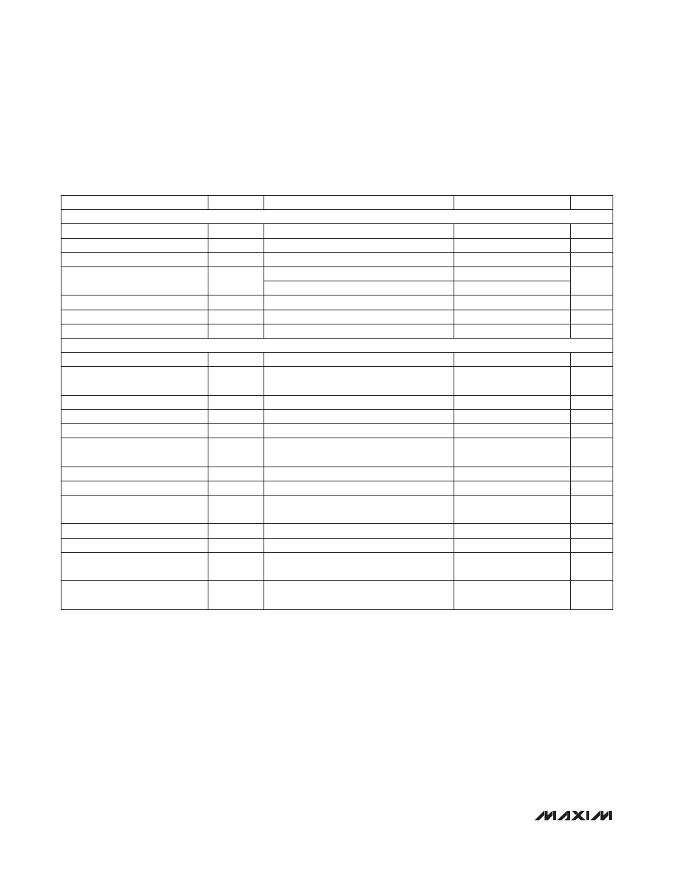
ELECTRICAL CHARACTERISTICS (continued)
(V
AGND
- V
EE
= 32V to 60V, T
A
= -40NC to +85NC, all voltages are referenced to V
EE
, unless otherwise noted. Typical values are at
V
AGND
- V
EE
= +54V, T
A
= +25NC. Currents are positive when entering the pin and negative otherwise.) (Note 2)
PARAMETER
SYMBOL
CONDITIONS
MIN
TYP
MAX
UNITS
ADC PERFORMANCE (Power-On Mode)
Resolution
9
Bits
Range
1.507
A
LSB Step Size
2.95
mA
Gain Error
T
A
= +25NC
2
%
T
A
= -40NC to +85NC
4
ADC Absolute Accuracy
I
OUT
= 400mA
130
136
142
LSB
Integral Nonlinearity
INL
0.3
1.7
LSB
Differential Nonlinearity
DNL
0.3
1.7
LSB
TIMING CHARACTERISTICS (For 2-Wire Fast Mode)
Serial Clock Frequency
f
SCL
400
kHz
Bus Free Time Between a STOP
and START Condition
tBUF
1.3
µs
Hold Time for a START Condition
t
HD,STA
0.6
µs
Low Period of the SCL Clock
t
LOW
1.3
µs
High Period of the SCL Clock
t
HIGH
0.6
µs
Setup Time for a Repeated
START Condition (Sr)
t
SU,STA
0.6
µs
Data Hold Time
t
HD,DAT
0
150
ns
Data in Setup Time
t
SU,DAT
100
ns
Rise Time of Both SDA and SCL
Signals, Receiving
t
R
(Note 9)
20 +
0.1C
B
300
ns
Fall Time of SDA Transmitting
t
F
(Note 9)
250
ns
Setup Time for STOP Condition
t
SU,STO
0.6
µs
Capacitive Load for Each
Bus Line
C
B
(Note 9)
400
pF
Pulse Width of Spike Suppressed
t
SP
(Note 9)
50
ns