Rainbow Electronics MAX5971B User Manual
Page 38
38 _____________________________________________________________________________________
MAX5971B
Single-Port, 40W, IEEE 802.3af/at,
PSE Controller with I
2
C
mode. When DET_BY is set to 1 however, the MAX5971B
can power the port without doing the detection routine.
AC_TH[2:0] (R23h[2:0]) allows direct programming of
the AC disconnect threshold. The threshold is defined
as a current since the comparator verifies that the peak
current pulses sensed at the DET input exceeds a preset
threshold. The current threshold is defined as follows:
I
AC_TH
= 85.28FA + 10.64FA x N
AC_TH
where N
AC_TH
is the decimal value of AC_TH[2:0]. The
default N
AC_TH
is 4 (AC_TH[2:0] = 100) which corre-
sponds to a default I
AC_TH
of ~128FA.
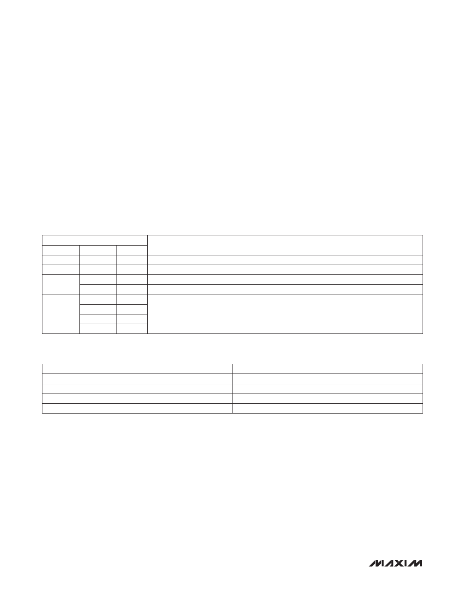
PWM Register (R24h)
The PWM register (R24h, Table 33) is used to program
the PWM duty cycle. On a power-up or after a reset
condition, this register is set to a default value of 0x00h.
PWM_TH[1:0] (R24h[5:4]) is used to set the PWM duty
cycle. The default PWM_TH[1:0] value of 00 corresponds
to a 6.25% duty cycle, while the maximum PWM_TH[1:0]
value of 11 corresponds to a 25% duty cycle (see Table 34).
Table 33. PWM Register
Table 34. PWM Duty-Cycle Settings
PWM_TH[1:0]
DUTY CYCLE (%)
00
6.25
01
12.5
10
18.75
11
25.0
ADDRESS = 24h
DESCRIPTION
SYMBOL
BIT NO.
R/W
Reserved
7
—
Reserved
Reserved
6
—
Reserved
PWM_TH
5
R/W
PWM_TH[1]
4
R/W
PWM_TH[0]
Reserved
3
R/W
Internally connected. For a write command, always write a zero to this bit.
2
R/W
1
R/W
0
R/W