Rainbow Electronics MAX5971B User Manual
Page 27
______________________________________________________________________________________ 27
MAX5971B
Single-Port, 40W, IEEE 802.3af/at,
PSE Controller with I
2
C
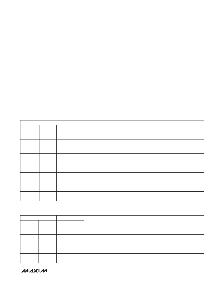
Interrupt Mask Register (R01h)
The interrupt mask register (R01h, Table 8) contains
MASK_ bits that mask the corresponding interrupt bits
in register R00h (active high). Setting MASK_ bits low
individually disables the corresponding interrupt signal.
When masked (set low), the corresponding bits are still
set in the interrupt register (R00h) but the masking bit
(R01h) suppresses the generation of an interrupt signal
(INT). On power-up or a reset condition, the interrupt
mask register is set to a default state of A4h.
The Event Registers (R02h to R08h)
Power Event Register (R02h/R03h)
The power event register (R02h/R03h, Table 9) records
changes in the power status of the port. On power-up or
after a reset condition, the power event register is set to
a default value of 00h. Any change in PGOOD (R10h[4])
sets PG_CHG to 1. Any change in PWR_EN (R10h[0])
sets PWEN_CHG to 1. PG_CHG and PWEN_CHG trig-
ger on the edges of PGOOD and PWR_EN and do not
depend on the actual logic status of the bits. The power
event register has two addresses. When read through
the R02h address, the content of the register is left
unchanged. When read through the CoR R03h address,
the register content is reset to the default state.
Table 8. Interrupt Mask Register
Table 9. Power Event Register
ADDRESS = 01h
DESCRIPTION
SYMBOL
BIT NO.
TYPE
MASK7
7
R/W
Interrupt mask bit 7. A logic-high enables the SUP_INT interrupts. A logic-low disables the
SUP_FLT interrupts.
Reserved
6
R/W
Reserved
MASK5
5
R/W
Interrupt mask bit 5. A logic-high enables the IMAX_INT interrupts. A logic-low disables the
IMAX_FLT interrupts.
MASK4
4
R/W
Interrupt mask bit 4. A logic-high enables the CL_INT interrupts. A logic-low disables the
CL_END interrupts.
MASK3
3
R/W
Interrupt mask bit 3. A logic-high enables the DET_INT interrupts. A logic-low disables the
DET_END interrupts.
MASK2
2
R/W
Interrupt mask bit 2. A logic-high enables the LD_INT interrupts. A logic-low disables the
LD_DISC interrupts.
MASK1
1
R/W
Interrupt mask bit 1. A logic-high enables the PG_INT interrupts. A logic-low disables the
PG_INT interrupts.
MASK0
0
R/W
Interrupt mask bit 0. A logic-high enables the PE_INT interrupts. A logic-low disables the
PE_INT interrupts.
ADDRESS =
02h
03h
DESCRIPTION
SYMBOL
BIT NO.
TYPE
R/W
Reserved
7
—
—
Reserved
Reserved
6
—
—
Reserved
Reserved
5
—
—
Reserved
PG_CHG
4
R
CoR
PGOOD change event for the port
Reserved
3
—
—
Reserved
Reserved
2
—
—
Reserved
Reserved
1
—
—
Reserved
PWEN_CHG
0
R
CoR
Power enable change event for the port