Electrical characteristics, Absolute maximum ratings – Rainbow Electronics MAX5971B User Manual
Page 2
2 ______________________________________________________________________________________
MAX5971B
Single-Port, 40W, IEEE 802.3af/at,
PSE Controller with I
2
C
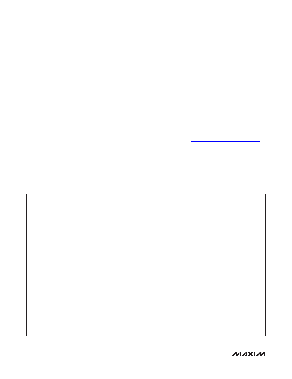
Stresses beyond those listed under “Absolute Maximum Ratings” may cause permanent damage to the device. These are stress ratings only, and functional
operation of the device at these or any other conditions beyond those indicated in the operational sections of the specifications is not implied. Exposure to absolute
maximum rating conditions for extended periods may affect device reliability.
(Voltages referenced to V
EE
, unless otherwise noted.)
AGND, DET, LED ..................................................-0.3V to +80V
OUT .......................................................-0.3V to (AGND + 0.3V)
OUTP ........................................................-6V to (AGND + 0.3V)
V
EE_DIG
................................................................-0.3V to +0.3V
OSC .........................................................................-0.3V to +6V
EN, PWMEN, MIDSPAN, LEGACY, ILIM1, ILIM2 ....-0.3V to +4V
INT, AD0, SCL, SDA ................................................-0.3V to +6V
Maximum Current into INT and SDA ..................................80mA
Maximum Current into LED ................................................40mA
Maximum Current into OUT ........................Internally Regulated
Continuous Power Dissipation (T
A
= +70NC)
28-Pin TQFN (derate 34.5mW/NC above +70NC) ......2758mW
Package Thermal Resistance (Note 1)
B
JA
...............................................................................29NC/W
B
JC
.................................................................................2NC/W
Operating Temperature Range .......................... -40NC to +85NC
Storage Temperature Range ............................ -65NC to +150NC
Junction Temperature .....................................................+150NC
Lead Temperature (soldering, 10s) ................................+300NC
Soldering Temperature (reflow) ......................................+260NC
ELECTRICAL CHARACTERISTICS
(V
AGND
- V
EE
= 32V to 60V, T
A
= -40NC to +85NC, all voltages are referenced to V
EE
, unless otherwise noted. Typical values are at
V
AGND
- V
EE
= +54V, T
A
= +25NC. Currents are positive when entering the pin and negative otherwise.) (Note 2)
ABSOLUTE MAXIMUM RATINGS
Note 1: Package thermal resistances were obtained using the method described in JEDEC specification JESD51-7, using a four-
layer board. For detailed information on package thermal considerations, refer to
PARAMETER
SYMBOL
CONDITIONS
MIN
TYP
MAX
UNITS
POWER SUPPLIES
Operating Voltage Range
V
AGND
V
AGND
- V
EE
32
60
V
Supply Current
I
EE
V
OUT
= V
EE
, all logic inputs unconnected,
measured at AGND in power mode
2.5
4
mA
CURRENT LIMIT
Current Limit
I
LIM
Maximum
I
LOAD
allowed
during
current-limit
conditions,
V
OUT
= 0V
(Note 3)
Class 0, 1, 2, 3 or ICUT
= 000
400
420
441
mA
Class 4 or ICUT = 001
684
720
756
Class 5 if ILIM1 = V
EE
,
ILIM2 = unconnected or
ICUT = 101
807
850
893
Class 5 if ILIM1 =
unconnected, ILIM2 = V
EE
or ICUT = 110
855
900
945
Class 5 if ILIM1 = V
EE
,
ILIM2 = V
EE
or ICUT = 111
902
950
998
Foldback Initial OUT Voltage
V
FLBK_ST
V
AGND
- V
OUT
below which the current limit
starts folding back
27
V
Foldback Final OUT Voltage
V
FLBK_END
V
AGND
- V
OUT
below which the current limit
reaches I
TH_FB
10
V
Minimum Foldback Current-Limit
Threshold
I
TH_FB
V
OUT
= V
AGND
166
mA