Rainbow Electronics MAX5971B User Manual
Page 31
______________________________________________________________________________________ 31
MAX5971B
Single-Port, 40W, IEEE 802.3af/at,
PSE Controller with I
2
C
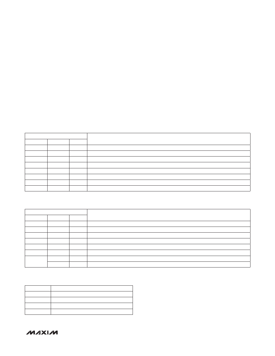
Pin Status Register (R11h)
The pin status register (R11h, Table 17) records the state
of the OSC, LEGACY, and MIDSPAN pins. The states
of OSC, LEGACY, and MIDSPAN are latched into the
corresponding bits after a power-up or reset condition
clears. Therefore, the default state of the pin status reg-
ister depends on those inputs (0000 to xxx1). Changes
to those inputs during normal operation are ignored and
do not change the register contents.
Configuration Registers (R12h to R17h)
Mode Register (R12h)
The mode register (R12h, Table 18) contains two bits that
set the MAX5971B mode of operation. Table 19 details
how to set the mode of operation for the device. On a
power-up or after a reset condition, the mode register is
set to a default value of 03h. Use software to program
the mode of operation. The software port specific reset
using RESET_P (R1Ah[0], Table 27) does not affect the
mode register. Setting POFF_CL (R12h[3]) to 1 prevents
power-up after a classification failure.
Table 17. Pin Status Register
Table 18. Mode Register
Table 19. Port Operating Mode Status
MODE
DESCRIPTION
00
Shutdown
01
Manual
10
Semiautomatic
11
Auto (Automatic)
To ADDRESS = 11h
DESCRIPTION
SYMBOL
BIT NO.
TYPE
Reserved
7
—
Reserved
Reserved
6
—
Reserved
Reserved
5
—
Reserved
Reserved
4
—
Reserved
OSC
3
R
OSC input latched-in status
LEGACY
2
R
LEGACY input latched-in status
MIDSPAN
1
R
MIDSPAN input latched-in status
Reserved
0
—
Reserved
ADDRESS = 12h
DESCRIPTION
SYMBOL
BIT NO.
TYPE
Reserved
7
—
Reserved
Reserved
6
—
Reserved
Reserved
5
—
Reserved
Reserved
4
—
Reserved
POFF_CL
3
R/W
A logic-high prevents power-up after a classification failure (I > 50mA, valid only in auto mode)
Reserved
2
—
Reserved
P_M
1
R/W
MODE[1] for the port
0
R/W
MODE[0] for the port