Pin description pin configuration – Rainbow Electronics MAX5971B User Manual
Page 12
12 _____________________________________________________________________________________
MAX5971B
Single-Port, 40W, IEEE 802.3af/at,
PSE Controller with I
2
C
Pin Description
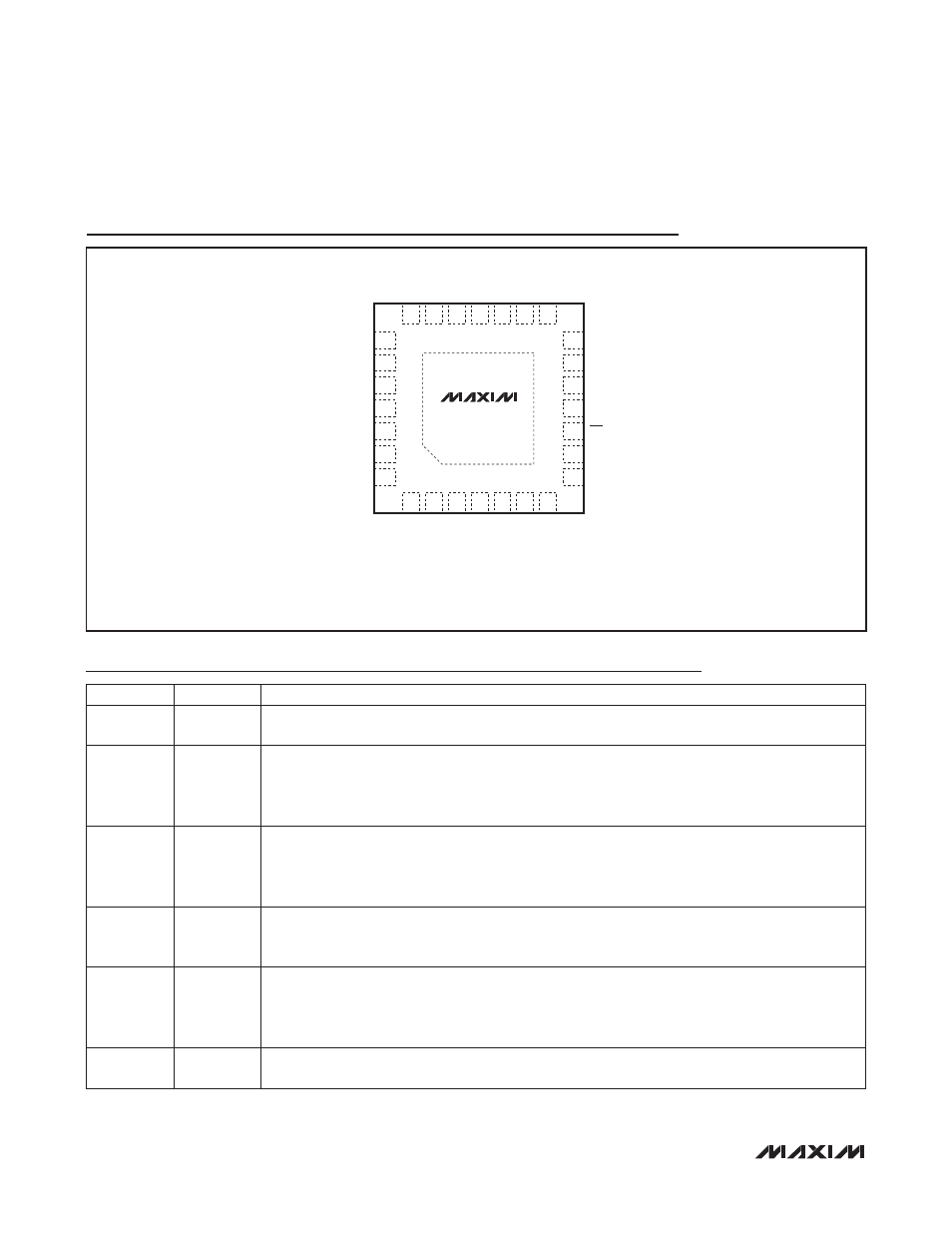
Pin Configuration
26
27
25
24
10
9
11
V
EE
ILIM1
ILIM2
PWMEN
MIDSPAN
12
V
EE
N.C.
N.C.
LED
AGND
N.C.
I.C.
1
2
OUTP
4
5
6
7
20
21
19
17
16 15
OUT
OUT
V
EE_DIG
AD0
INT
SCL
MAX5971B
V
EE
OSC
3
18
28
8
N.C.
SDA
N.C.
23
13 LEGACY
DET
22
14 EN
*CONNECT TO V
EE
.
*EP
N.C.
THIN QFN
TOP VIEW
+
PIN
NAME
FUNCTION
1, 2, 3
V
EE
Analog Low-Side Supply Input. Bypass with an external 100V, 47FF capacitor in parallel with a
100V, 0.1FF ceramic capacitor between AGND and V
EE
.
4
ILIM1
Class 5 Current-Limit Digital Adjust 1. Referenced to V
EE
. ILIM1 is internally pulled up to the digital
supply. Use ILIM1 with ILIM2 to enable Class 5 operation and to adjust the Class 5 current-limit
value. See the Electrical Characteristics table and Table 3 in the Class 5 PD Classification section
for details.
5
ILIM2
Class 5 Current-Limit Digital Adjust 2. Referenced to V
EE
. ILIM2 is internally pulled up to the digital
supply. Use ILIM2 with ILIM1 to enable Class 5 operation and to adjust the Class 5 current-limit
value. See the Electrical Characteristics table and Table 3 in the Class 5 PD Classification section
for details.
6
PWMEN
PWM Control Logic Input. Referenced to V
EE
. PWMEN is internally pulled up to the digital sup-
ply. Leave unconnected to enable the internal PWM to drive the LED pin. Force low to disable the
internal PWM.
7
MIDSPAN
Detection Collision Avoidance Logic Input. Referenced to V
EE
. MIDSPAN is internally pulled up
to the digital supply. Leave unconnected to activate the detection collision avoidance circuitry
for midspan PSE systems. Force low to disable this function for an end-point PSE system. The
MIDSPAN logic level latches after the device is powered up or after a reset condition.
8
SDA
2-Wire Serial Interface Input/Output Data Line. Referenced to V
EE
. Connect to V
EE
if the I
2
C inter-
face is not used.