Rainbow Electronics MAX5971B User Manual
Page 21
______________________________________________________________________________________ 21
MAX5971B
Single-Port, 40W, IEEE 802.3af/at,
PSE Controller with I
2
C
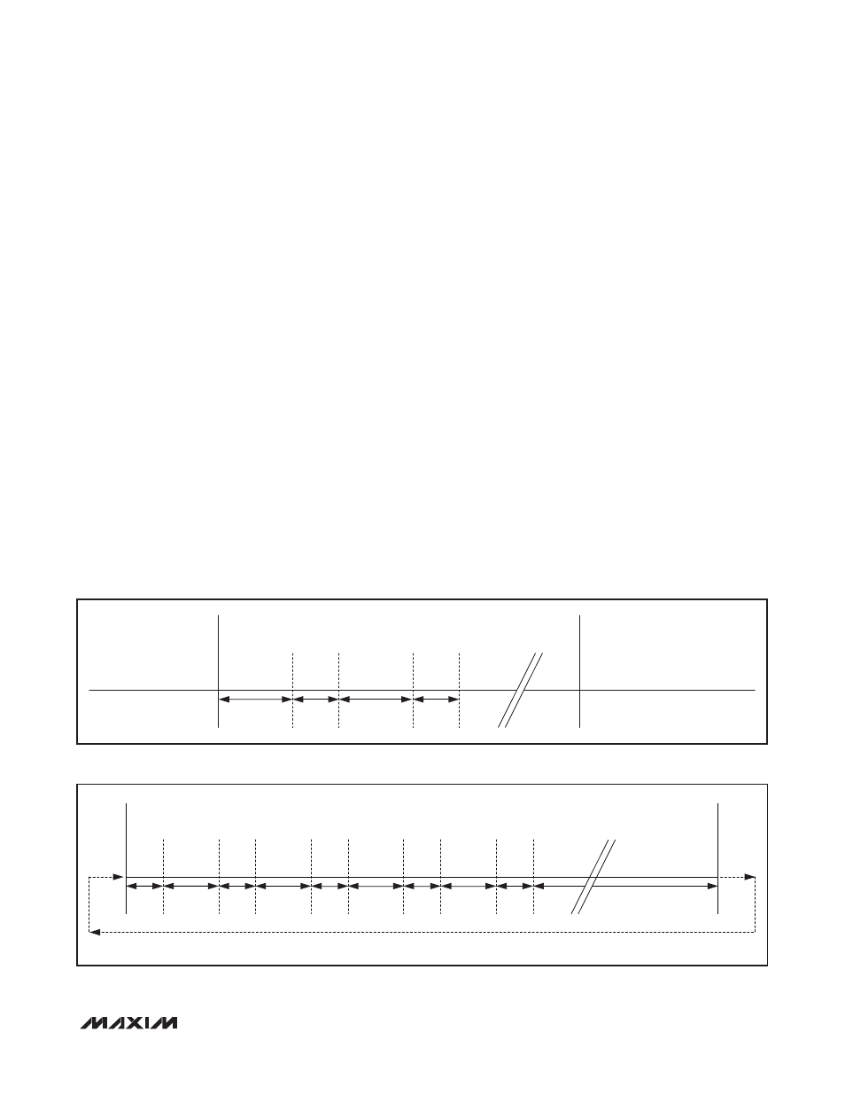
Figure 4. LED Code Timing for Overcurrent Fault During Port Power-On
Figure 5. LED Code Timing for Detection Fault Due to High- or Low-Discovery Signature Resistance
40V (typ). A fault latches into the supply event regis-
ter V
EE_UV
(R0Ah[2] and R0Bh[2], Table 12) but the
MAX5971B does not power down the port in this case.
DC Disconnect Monitoring
Force OSC to V
EE
and power or reset the device to acti-
vate DC load-disconnect monitoring. DCD_EN (R13h[0])
is set to 1 to enable DC load disconnect. If I
RSENSE
(the
current across R
SENSE
) falls below the DC load-discon-
nect threshold, I
DCTH
, for more than t
DISC
, the device
turns off port power and sets LD_DISC in the fault event
registers (R06h[4] and R07h[4]) to 1.
AC Disconnect Monitoring
The MAX5971B features AC load-disconnect monitoring.
Bypass OSC with a 100nF (Q10% tolerance) external
capacitor to V
EE
and power or reset the device to auto-
matically enable AC disconnect. ACD_EN (R13h[4]) is
set to 1 to enable AC disconnect (the bypass from OSC
to V
EE
must be in place as well). When AC disconnect
is enabled, a blocking diode in series to OUT and an
RC circuit in parallel to the DET diode must be used, as
shown in the typical operating circuit of Figure 16.
The AC disconnect uses an internal triangle-wave gen-
erator to supply the probing signal. Then the resulting
4V
P-P
amplitude wave is forced on DET. The common
mode of the output signal probed on DET is 5V below
AGND. If the AC current peak at DET falls below I
ACTH
for more than t
DISC
, the device powers down the port and
asserts LD_DISC (R06h[4] and R07h[4]). The AC load-
disconnect threshold (I
ACTH
) is programmable using the
AC_TH[2:0] bits (R23h[2:0], see Table 32 for settings).
PWM and LED Signals
The MAX5971B includes a multifunction LED driver to
inform the user of the port status. LED is an open-drain,
multifunction output referenced to V
EE
and can sink
10mA (typ) while driving an external LED. The LED is
turned on when the port is connected to a valid PD and
powered. If the port is not powered or is disconnected,
the LED is off.
For two other conditions, the MAX5971B blinks a code
to communicate the port status. A series of two flashes
indicates an overcurrent fault occurred during port pow-
er-on, and has a timing characteristic detailed by Figure
4. A series of five flashes indicates that during detection
an invalid low or high discovery signature resistance
was detected, and has a timing characteristic detailed
by Figure 5.
LED OFF
LED ON
223ms
LED ON
LED ON
LED ON
LED OFF
LED OFF
74ms
74ms
223ms
PORT POWERED DOWN, DUE TO OVERCURRENT FAULT
PORT POWERED ON
PORT POWERED ON AGAIN
LED
OFF
LED
ON
223ms
74ms
LED
OFF
LED
ON
223ms
74ms
LED
OFF
LED
ON
223ms
74ms
LED
OFF
LED
ON
223ms
74ms
LED
ON
74ms
LED
OFF
1.4s
SEQUENCE REPEATS
INVALID HIGH OR LOW
DISCOVERY SIGNATURE
RESISTANCE DETECTED