Register map and description – Rainbow Electronics MAX5971B User Manual
Page 26
26 _____________________________________________________________________________________
MAX5971B
Single-Port, 40W, IEEE 802.3af/at,
PSE Controller with I
2
C
Operation with Multiple Masters
When the MAX5971B operates on a 2-wire interface
with multiple masters, a master reading the MAX5971B
should use repeated starts between the write that sets
the MAX5971B’s address pointer, and the read(s) that
take the data from the location(s). It is possible for
master 2 to take over the bus after master 1 has set up
the MAX5971B’s address pointer but before master 1
has read the data. If master 2 subsequently resets the
MAX5971B’s address pointer, then master 1’s read may
be from an unexpected location.
Command Address Autoincrementing
Address autoincrementing allows the MAX5971B to be
configured with fewer transmissions by minimizing the
number of times the command address needs to be
sent. The command address stored in the MAX5971B
generally increments after each data byte is written or
read (Table 6). The MAX5971B is designed to prevent
overwrites on unavailable register addresses and unin-
tentional wraparound of addresses.
Register Map and Description
The MAX5971B contains a bank of volatile registers that
store its settings and status. The device features an I
2
C-
compatible, 2-wire serial interface, allowing the registers
to be fully software configurable and programmable. In
addition to this, several registers are also pin program-
mable to allow the MAX5971B to operate in auto mode
and still be partially configurable even without the assis-
tance of software.
The Interrupts Registers (R00h to R01h)
Interrupt Register (R00h)
The interrupt register (R00h, Table 7) summarizes the
event register status and is used to send an interrupt
signal to the controller. On power-up or after a reset
condition, interrupt (R00h) is set to a default value of
00h. INT goes low to report an interrupt event if any one
of the active interrupt bits is set to 1 (active high) and
it is not masked by the interrupt mask register (R01h,
Table 8). INT does not go low to report an interrupt if
the corresponding mask bit (R01h) is set. Writing a 1
to CLR_INT (R1Ah[7], Table 27) clears all interrupt and
events registers (resets to low). INT_EN (R17h[7], Table
25) is a global interrupt enable and writing a 0 to INT_EN
disables the INT output, putting it into a state of high
impedance.
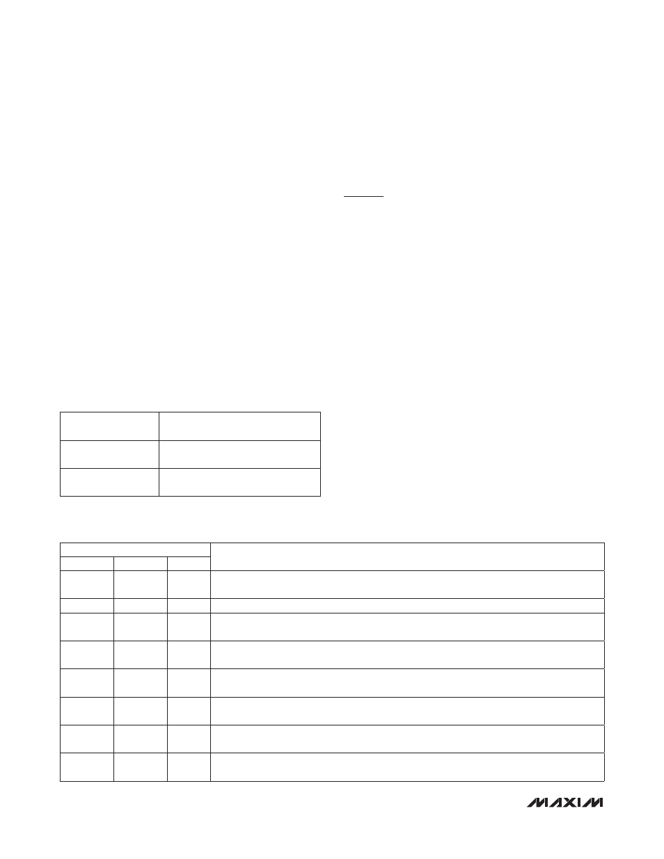
Table 6. Autoincrement Rules
Table 7. Interrupt Register
COMMAND BYTE
ADDRESS RANGE
AUTOINCREMENT BEHAVIOR
0x00 to 0x37
Command address autoincrements
after byte read or written
0x37
Command address remains at 0x37
after byte written or read
ADDRESS = 00h
DESCRIPTION
SYMBOL
BIT NO.
TYPE
SUP_INT
7
R
Interrupt signal for supply faults. SUP_INT is the logic OR of all the active bits in the supply
event register (R0Ah/R0Bh, Table 12).
Reserved
6
R
Reserved
IMAX_INT
5
R
Interrupt signal for current-limit violations. IMAX_INT reports the status of IMAX_FLT (bit 0) in
the fault event register (R06h/R07h, Table 11).
CL_INT
4
R
Interrupt signal for completion of classification. CL_INT reports the status of CL_END (bit 4)
in the detect event register (R04h/R05h, Table 10).
DET_INT
3
R
Interrupt signal for completion of detection. DET_INT reports the status of DET_END (bit 0) in
the detect event register (R04h/R05h, Table 10).
LD_INT
2
R
Interrupt signal for load disconnection. LD_INT reports the status of LD_DISC (bit 4) in the
fault event register (R06h/R07h, Table 11).
PG_INT
1
R
Interrupt signal for PGOOD (R10h[4]) status changes. PG_INT reports the status of PG_CHG
(bit 4) in the power event register (R02h/R03h, Table 9).
PE_INT
0
R
Interrupt signal for power enable status change. PEN_INT reports the status of PWEN_CHG
(bit 0) in the power event register (R02h/R03h, Table 9).