Pin configuration pin description – Rainbow Electronics MAX5970 User Manual
Page 8
0V to 16V, Dual Hot-Swap Controller with 10-Bit
Current and Voltage Monitor and 4 LED Drivers
MAX5970
8 ______________________________________________________________________________________
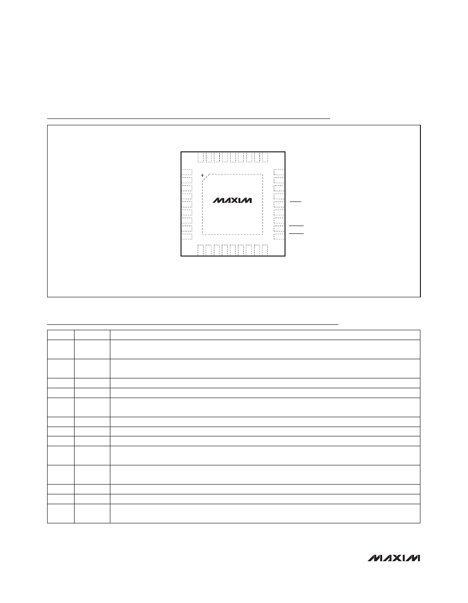
Pin Configuration
Pin Description
DGND
HWEN
PG1
ALERT
FAULT2
FAULT1
SCL
SDA
PG2
IN
AGND
REG
A1
A0
PROT
*EP = EXPOSED PAD.
EP*
IRNG2
1
2
3
4
5
6
7
8
9
10
11
12
13
14
15
16
17
18
36
35
34
33
32
31
30
29
28
27
26
25
24
23
22
21
20
19
LED1
LED2
POL
ON1
GND1
GATE1
MON1
SENSE1
MON2
SENSE2
GATE2
GND2
LED3
LED4
MODE
RETRY
ON2
TQFN
MAX5970
TOP VIEW
BIAS
DREG
IRNG1
PIN
NAME
FUNCTION
1
IRNG2
Channel 2 Three-State Current-Sense Range Selection Input. Set the circuit-breaker threshold range by
connecting to DGND, DREG, or leave unconnected.
2
IRNG1
Channel 1 Three-State Current-Sense Range Selection Input. Set the circuit-breaker threshold range by
connecting to DGND, DREG, or leave unconnected.
3
IN
Power-Supply Input. Connect to a voltage from 2.7V to 16V. Bypass to AGND with a 1FF capacitor.
4
AGND
Analog Ground. Connect all GND_ and DGND to AGND externally using a star connection.
5
REG
Internal Regulator Output. Bypass to ground with a 1FF capacitor. Connect only to DREG. Do not use to
power external circuitry.
6
BIAS
For normal operation, connect BIAS to REG.
7
A1
Three-State I
2
C Address Input 1
8
A0
Three-State I
2
C Address Input 0
9
PROT
Protection Behavior Input. Three-state input sets one of three different response options for undervoltage
and overvoltage events.
10
SENSE1
Channel 1 Current-Sense Input. Connect SENSE1 to the source of an external MOSFET and to one end of
R
SENSE1
.
11
MON1
Channel 1 Voltage Monitoring Input
12
GATE1
Channel 1 Gate-Drive Output. Connect to the gate of an external n-channel MOSFET.
13
GND1
Channel 1 Gate Discharge Current Ground Return. Connect all GND_ and DGND to AGND externally
using a star connection.