Rainbow Electronics MAX5970 User Manual
Page 37
0V to 16V, Dual Hot-Swap Controller with 10-Bit
Current and Voltage Monitor and 4 LED Drivers
MAX5970
______________________________________________________________________________________ 37
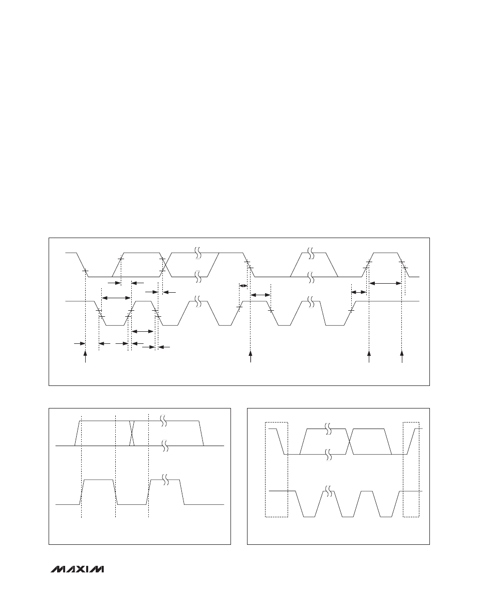
Figure 4. Serial-Interface Timing Details
Figure 5. Bit Transfer
Figure 6. START and STOP Conditions
The 2-wire communication is fully compatible with exist-
ing 2-wire serial interface systems; Figure 4 shows the
interface timing diagram. The MAX5970 is a transmit/
receive slave-only device, relying upon a master device
to generate a clock signal. The master device (typically
a microcontroller) initiates data transfer on the bus and
generates SCL to permit that transfer.
A master device communicates to the MAX5970 by
transmitting the proper address followed by command
and/or data words. Each transmit sequence is framed by
a START (S) or REPEATED START (Sr) condition and a
STOP (P) condition. Each word transmitted over the bus
is 8 bits long and is always followed by an acknowledge
pulse.
SCL is a logic input, while SDA is a logic input/open-
drain output. SCL and SDA both require external pullup
resistors to generate the logic-high voltage. Use 4.7kI
for most applications.
Bit Transfer
Each clock pulse transfers one data bit. The data
on SDA must remain stable while SCL is high (see
Figure 5), otherwise the MAX5970 registers a START or
STOP condition (see Figure 6) from the master. SDA and
SCL idle high when the bus is not busy.
STOP
CONDITION
REPEATED START
CONDITION
START
CONDITION
t
HIGH
t
LOW
t
R
t
F
t
SU:DAT
t
SU:STA
t
SU:STO
t
HD:STA
t
BUF
t
HD:STA
t
HD:DAT
SCL
SDA
START
CONDITION
DATA LINE STABLE,
DATA VALID
SDA
SCL
CHANGE OF
DATA ALLOWED
P
S
START
CONDITION
SDA
SCL
STOP
CONDITION