Rainbow Electronics MAX5970 User Manual
Page 32
0V to 16V, Dual Hot-Swap Controller with 10-Bit
Current and Voltage Monitor and 4 LED Drivers
MAX5970
32 _____________________________________________________________________________________
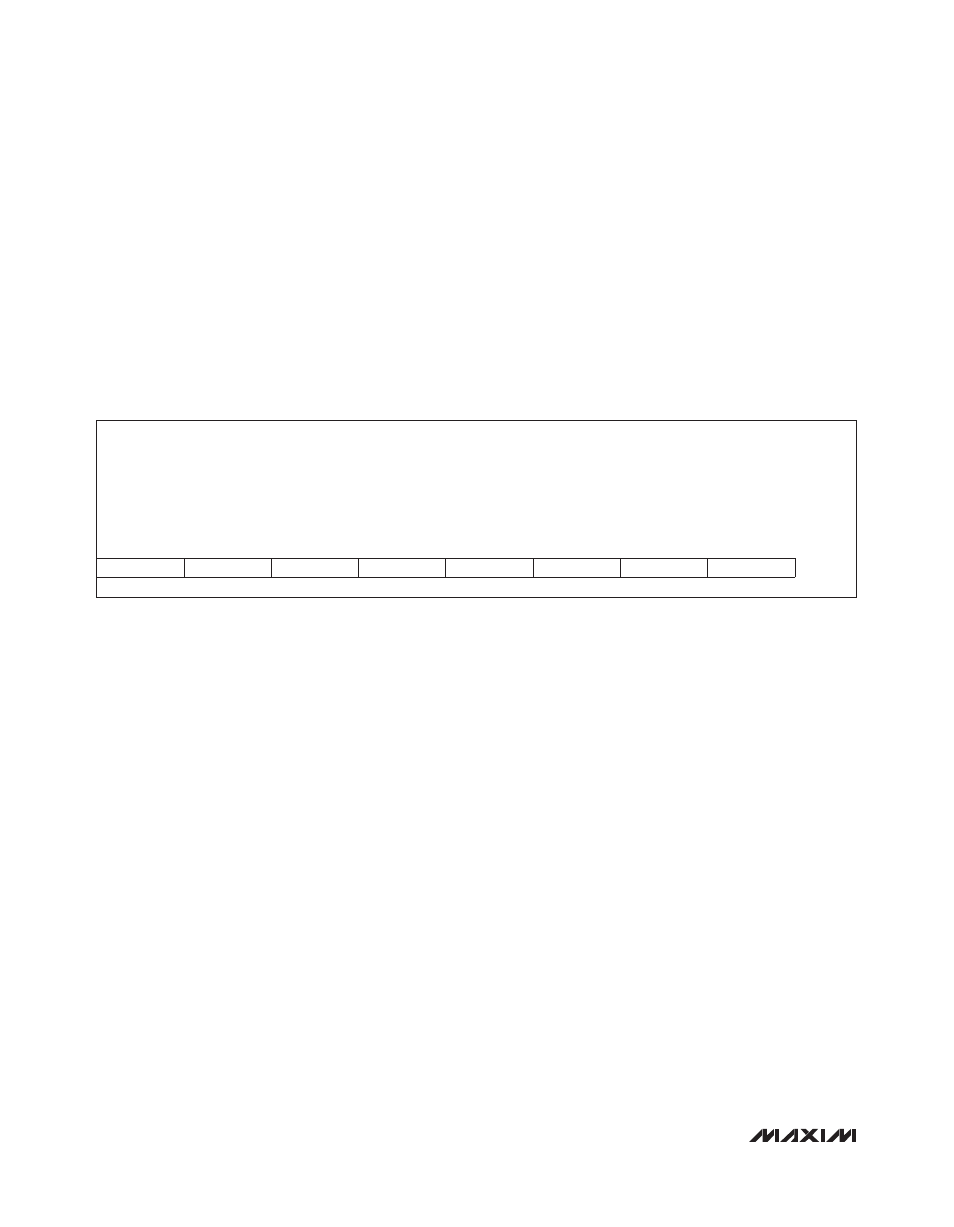
Table 44. Circular Buffer Stop-Delay Register Format
If the circular buffer contents are retrieved as 10-bit
data, the first byte read out is the high-order 8 bits of the
10-bit sample, and the second byte read out contains
the two least-significant bits (LSBs) of the sample. This is
repeated for each of the 50 samples in the buffer. Thus,
2 bytes must be read for each 10-bit sample retrieved.
Conversely, if the buffer contents are retrieved as 8-bit
data, then each byte read out contains the 8 MSB of
each successive sample. It is important to remember
that in 10-bit mode, 100 bytes must be read to extract the
entire buffer contents, but in 8-bit mode, only 50 bytes
must be read.
The circular buffer system has a user-programmable
stop delay that specifies a certain number of sample
cycles to continue recording to the buffer after a shut-
down occurs. This delay value is stored in register
cbuf_dly_stop[5:0] (see Table 44).
The default (reset) value of the buffer stop-delay is 25
samples, which means that an equal number of samples
are stored in the buffer preceding and following the
moment of the shutdown event. The buffer stop delay
is analogous to an oscilloscope trigger delay, because
it allows the MAX5970 to record what happened both
immediately before and after a shutdown. In other words,
when the contents of a circular buffer are read out of the
MAX5970, the shutdown event, by default, is located in
the middle of the recorded data. The balance of data
before and after an event can be altered by writing a dif-
ferent value (between 0 and 50) to the buffer stop-delay
register.
Autoretry or Latched-Off Fault Management
In the event of an overcurrent, undervoltage, or overvolt-
age condition that results in the shutdown of one or both
channels, the MAX5970 device can be configured to
either latch off or automatically restart the affected chan-
nel. The MAX5970 stays off if the RETRY input is set low
(latched-off), and automatically retries if the RETRY input
is high. The RETRY input is read once during initialization
and sets the value of status3[6] register (see Table 30).
The autoretry feature has a fixed 200ms timeout delay
between fault shutdown and the autorestart attempt. Be
aware that if the MAX5970 is configured for autoretry
operation, the startup event occurs every 200ms if a
short circuit occurs. A short circuit during startup causes
the output current to increase rapidly as the MOSFET
is enhanced, until the slow-trip threshold is reached
and the gate is pulled low again. Be sure to evaluate
MOSFET junction temperature rise for this repeated-
stress condition if autoretry is used.
To restart a channel that has been shutdown in latched-
off operation (RETRY low), the user must either cycle
power to the IN pin, or toggle one or more of the ON_
pin, Chx_EN1 bit, or the Chx_EN2 bit for the affected
channel.
Description:
Circular buffer stop-delay: any integer number between 0 and 50 samples that are to be recorded
to a buffer after a shutdown event, before the buffer stops storing new data.
Register Title:
cbuf_dly_stop
Register Address:
0x40
R
R
R
R
R
R
R
R
RESET
VALUE
0
0
0x19
bit 7
bit 6
bit 5
bit 4
bit 3
bit 2
bit 1
bit 0