Rainbow Electronics MAX5970 User Manual
Page 17
0V to 16V, Dual Hot-Swap Controller with 10-Bit
Current and Voltage Monitor and 4 LED Drivers
MAX5970
______________________________________________________________________________________ 17
from 40% to 100% of the selected full-scale current-
sense range. The slow-trip threshold follows the fast-trip
threshold as one of four programmable ratios, set by the
ifast2slow register (see Tables 5a and 5b).
The fast-trip threshold is always higher than the slow-trip
threshold, and the fast-trip comparator responds very
quickly to protect the system against sudden, severe
overcurrent events. The slower response of the slow-
trip comparator varies depending upon the amount of
overdrive beyond the slow-trip threshold. If the overdrive
is small and short-lived, the comparator does not shut
down the affected channel. As the overcurrent event
increases in magnitude, the response time of the slow-
trip comparator decreases. This scheme provides good
rejection of noise and spurious overcurrent transients
near the slow-trip threshold while aggressively protect-
ing the system against larger overcurrent events that
occur as a result of a load fault.
Setting Circuit-Breaker Thresholds
To select and set the MAX5970 slow-trip and fast-trip
comparator thresholds, use the following procedure:
1) Select one of four ratios between the fast-trip thresh-
old and the slow-trip threshold: 200%, 175%, 150%,
or 125%. A system that experiences brief, but large
transient load currents should use a higher ratio,
whereas a system that operates continuously at
higher average load currents might benefit from a
smaller ratio to ensure adequate protection. The ratio
is set by writing to the ifast2slow register. The default
setting on power-up is 200%.
2) Determine the slow-trip threshold V
TH,ST
based on the
anticipated maximum continuous load current during
normal operation, and the value of the current-sense
resistor. The slow-trip threshold should include some
margin (possibly 20%) above the maximum load
current to prevent spurious circuit-breaker shutdown
and to accommodate passive component tolerances:
V
TH,ST
= R
SENSE
x I
LOAD,MAX
x 120%
3) Calculate the necessary fast-trip threshold V
TH,FT
based on the ratio set in step 1:
V
TH,FT
= V
TH,ST
x (ifast2slow ratio)
4) Select one of the four maximum current-sense
ranges: 25mV, 50mV, or 100mV. The current-sense
range is initially set upon power-up by the state of
the associated IRNG_ input, but can be altered at any
time by writing to the status2 register. For maximum
accuracy and best measurement resolution, select
the lowest current-sense range that is larger than the
V
TH,FT
value calculated in Step 3.
5) Program the fast-trip and slow-trip thresholds by writ-
ing an 8-bit value to the dac_chx register. This 8-bit
value is determined from the desired V
TH,ST
value
that was calculated in Step 2, the threshold ratio from
Step 1, and the current-sense range from Step 4:
DAC = V
TH,ST
x 255 x (ifast2slow ratio)/
(IRNG_ current-sense range)
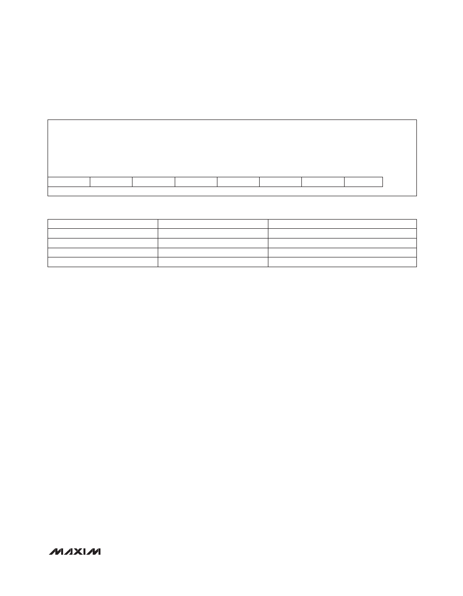
Table 5a. ifast2slow Register Format
Table 5b. Setting Fast-Trip to Slow-Trip Threshold Ratio
Description:
Current threshold fast to slow setting bits
Register Title:
ifast2slow
Register Address:
0x30
R/W
R/W
R/W
R/W
R/W
R/W
R/W
R/W
RESET
VALUE
—
—
—
—
Ch2_FS1
Ch2_FS0
Ch1_FS1
Ch1_FS0
0x0F
bit 7
bit 6
bit 5
bit 4
bit 3
bit 2
bit 1
bit 0
Chx_FS1
Chx_FS0
FAST-TRIP TO SLOW-TRIP RATIO (%)
0
0
125
0
1
150
1
0
175
1
1
200