Rainbow Electronics MAX5970 User Manual
Page 20
0V to 16V, Dual Hot-Swap Controller with 10-Bit
Current and Voltage Monitor and 4 LED Drivers
MAX5970
20 _____________________________________________________________________________________
Digital Current Monitoring
The two current-sense signals are sampled by the inter-
nal 10-bit 10ksps ADC, and the most recent results are
stored in registers for retrieval through the I
2
C interface.
The current conversion values are 10 bits wide, with the
eight high-order bits written to one 8-bit register and the
two low-order bits written to the next higher 8-bit register
address (Tables 9 and 10). This allows use of just the
high-order byte in applications where 10-bit precision is
not required. This split 8-bit/2-bit storage scheme is used
throughout the MAX5970 for all 10-bit ADC conversion
results and 10-bit digital comparator thresholds.
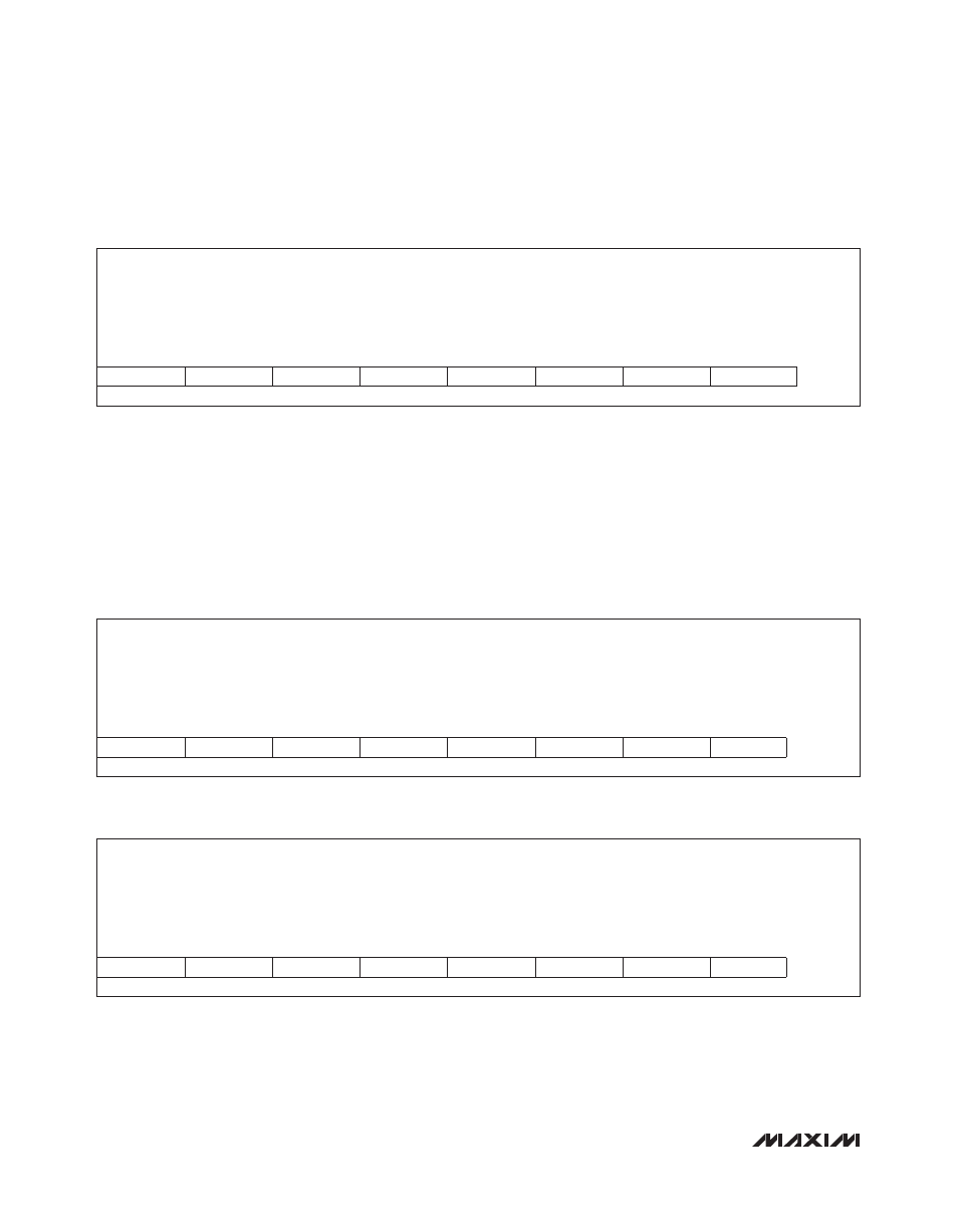
Table 8. dac_chx Register Format
Table 9. ADC Current Conversion Results Register Format (High-Order Bits)
Table 10. ADC Current Conversion Results Register Format (Low-Order Bits)
Description:
Fast-comparator threshold DAC setting
Register Title:
dac_ch0
dac_ch1
Register Addresses:
0x2E
0x2F
R/W
R/W
R/W
R/W
R/W
R/W
R/W
R/W
RESET
VALUE
DAC[7]
DAC[6]
DAC[5]
DAC[4]
DAC[3]
DAC[2]
DAC[1]
DAC[0]
0xBF
bit 7
bit 6
bit 5
bit 4
bit 3
bit 2
bit 1
bit 0
Description:
Most recent current conversion result, high-order bits [9:2]
Register Title:
adc_ch0_cs_msb
adc_ch1_cs_msb
Register Addresses:
0x00
0x04
R
R
R
R
R
R
R
R
RESET
VALUE
inew_9
inew_8
inew_7
inew_6
inew_5
inew_4
inew_3
inew_2
0x00
bit 7
bit 6
bit 5
bit 4
bit 3
bit 2
bit 1
bit 0
Description:
Most recent current conversion result, low-order bits [0:1]
Register Title:
adc_ch0_cs_ lsb
adc_ch1_cs_lsb
Register Addresses:
0x01
0x05
R
R
R
R
R
R
R
R
RESET
VALUE
inew_1
inew_0
0x00
bit 7
bit 6
bit 5
bit 4
bit 3
bit 2
bit 1
bit 0