Pin description – Rainbow Electronics MAX19985A User Manual
Page 18
MAX19985A
Dual, SiGe, High-Linearity, 700MHz to 1000MHz
Downconversion Mixer with LO Buffer/Switch
18
______________________________________________________________________________________
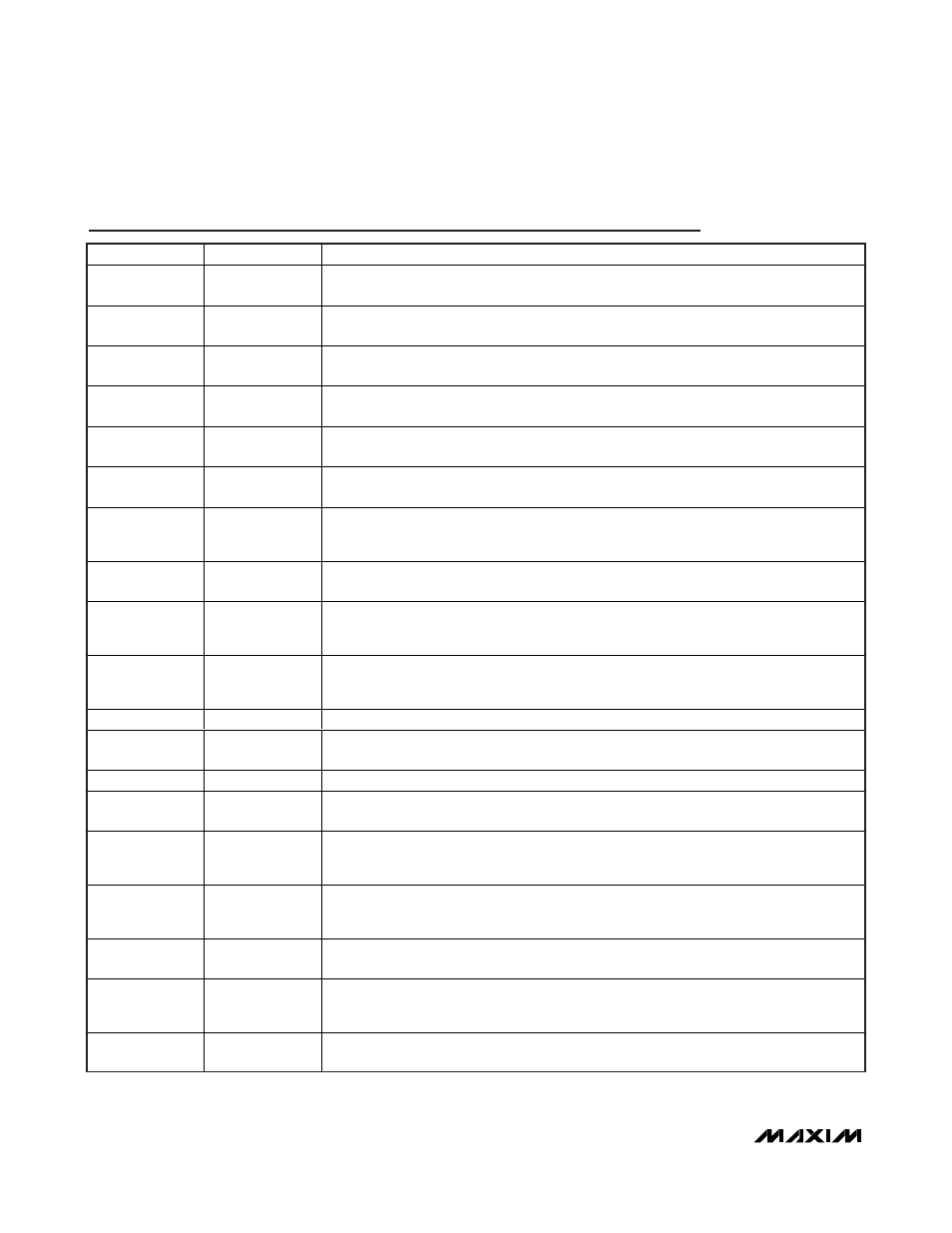
Pin Description
PIN
NAME
FUNCTION
1
RFMAIN
Main Channel RF input. Internally matched to 50
Ω. Requires an input DC-blocking
capacitor.
2
TAPMAIN
Main Channel Balun Center Tap. Bypass to GND with 39pF and 0.033µF capacitors as
close as possible to the pin with the smaller value capacitor closer to the part.
3, 5, 7, 12, 20, 22,
24, 25, 26, 34
GND
Ground
4, 6, 10, 16, 21,
30, 36
V
CC
Power Supply. Bypass to GND with 0.01µF capacitors as close as possible to the pin. Pins
4 and 6 do not require bypass capacitors.
8
TAPDIV
Diversity Channel Balun Center Tap. Bypass to GND with 39pF and 0.033µF capacitors as
close as possible to the pin with the smaller value capacitor closer to the part.
9
RFDIV
Diversity Channel RF Input. Internally matched to 50
Ω. Requires an input DC-blocking
capacitor.
11
IFDBIAS
IF Diversity Amplifier Bias Control. Connect a resistor from this pin to ground to set the bias
current for the diversity IF amplifier (see the Typical Operating Characteristics for typical
performance vs. resistor value).
13, 14
IFD+, IFD-
Diversity Mixer Differential IF Outputs. Connect pullup inductors from each of these pins to
V
CC
(see the Typical Application Circuit).
15
LEXTD
Diversity External Inductor Connection. Connect a parallel combination of an inductor and
a 500
Ω resistor from this pin to ground to increase the RF-to-IF and LO-to-IF isolation (see
the Typical Operating Characteristics for typical performance vs. inductor value).
17
LODBIAS
LO Diversity Amplifier Bias Control. Connect a resistor from this pin to ground to set the
bias current for the diversity LO amplifier (see the Typical Operating Characteristics for
typical performance vs. resistor value).
18, 28
N.C.
No Connection. Not internally connected.
19
LO1
Local Oscillator 1 Input. This input is internally matched to 50
Ω. Requires an input DC-
blocking capacitor.
23
LOSEL
Local Oscillator Select. Set this pin to high to select LO1. Set to low to select LO2.
27
LO2
Local Oscillator 2 Input. This input is internally matched to 50
Ω. Requires an input DC-
blocking capacitor.
29
LOMBIAS
LO Main Amplifier Bias Control. Connect a resistor from this pin to ground to set the bias
current for the main LO amplifier (see the Typical Operating Characteristics for typical
performance vs. resistor value).
31
LEXTM
Main External Inductor Connection. Connect a parallel combination of an inductor and a
500
Ω resistor from this pin to ground to increase the RF-to-IF and LO-to-IF isolation (see
Typical Operating Characteristics for typical performance vs. inductor value).
32, 33
IFM-, IFM+
Main Mixer Differential IF Outputs. Connect pullup inductors from each of these pins to V
CC
(see the Typical Application Circuit).
35
IFMBIAS
IF Main Amplifier Bias Control. Connect a resistor from this pin to ground to set the bias
current for the main IF amplifier (see the Typical Operating Characteristics for typical
performance vs. resistor value).
—
EP
Exposed Pad. Internally connected to GND. Connect to a large ground plane using
multiple vias to maximize thermal and RF performance.