3v supply ac electrical characteristics – Rainbow Electronics MAX19995 User Manual
Page 6
MAX19995
Dual, SiGe, High-Linearity, 1700MHz to 2200MHz
Downconversion Mixer with LO Buffer/Switch
6
_______________________________________________________________________________________
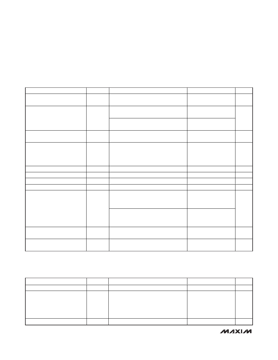
+5.0V SUPPLY AC ELECTRICAL CHARACTERISTICS (continued)
(
Typical Application Circuit optimized for the DCS/PCS band, R1 = R4 = 806
Ω, R2 = R5 = 2.32kΩ, V
CC
= +4.75V to +5.25V, RF and
LO ports are driven from 50
Ω sources, P
LO
= -3dBm to +3dBm, PRF = -5dBm, f
RF
= 1700MHz to 2000MHz, f
LO
= 1510MHz to
1810MHz, f
IF
= 190MHz, f
RF
> f
LO
, T
C
= -40°C to +85°C. Typical values are at V
CC
= +5.0V, P
RF
= -5dBm, P
LO
= 0dBm,
fRF = 1800MHz, f
LO
= 1610MHz, f
IF
= 190MHz, T
C
= +25°C, unless otherwise noted.) (Note 6)
PARAMETER
SYMBOL
CONDITIONS
MIN
TYP
MAX
UNITS
RF Input Return Loss
LO and IF terminated into matched
impedance, LO on
21
dB
LO port selected, RF and IF terminated into
matched impedance
20
LO Input Return Loss
LO port unselected, RF and IF terminated
into matched impedance
19
dB
IF Output Impedance
Z
IF
Nominal differential impedance of the IC’s
IF outputs
200
Ω
IF Return Loss
RF terminated into 50
Ω, LO driven by 50Ω
source, IF transformed to 50
Ω using
external components shown in Typical
Application Circuit
12.5
dB
RF-to-IF Isolation
f
RF
= 1700MHz for min value
30
39
dB
LO Leakage at RF Port
(Notes 8, 10)
-31
-24.7
dBm
2LO Leakage at RF Port
(Note 8)
-20
-16
dBm
LO Leakage at IF Port
(Note 8)
-40
-27
dBm
RFMAIN converted power measured at
IFD_, relative to IFM_, all unused ports
terminated to 50
Ω
40
49
Channel Isolation
RFDIV converted power measured at IFM_,
relative to IFD_, all unused ports terminated
to 50
Ω
40
49
dB
LO-to-LO Isolation
P
LO1
= +3dBm, P
LO2
= +3dBm,
f
LO1
= 1610MHz, f
LO2
= 1611MHz
40
56
dB
LO Switching Time
50% of LOSEL to IF settled within 2
degrees
50
ns
+3.3V SUPPLY AC ELECTRICAL CHARACTERISTICS
(
Typical Application Circuit. Typical values are at V
CC
= +3.3V, P
RF
= -5dBm, P
LO
= 0dBm, f
RF
= 1800MHz, f
LO
= 1610MHz,
f
IF
= 190MHz, T
C
= +25°C, unless otherwise noted.) (Note 6)
PARAMETER
SYMBOL
CONDITIONS
MIN
TYP
MAX
UNITS
Conversion Gain
G
C
8.4
dB
Conversion Gain Flatness
Flatness over any one of three frequency
bands:
f
RF
= 1710MHz to 1785MHz
f
RF
= 1850MHz to 1910MHz
f
RF
= 1920MHz to 1980MHz
±0.1
dB
G ai n V ar i ati on Over Tem p er atur e
TC
CG
T
C
= -40°C to +85°C
-0.009
dB/°C