Operating instructions, 9985 function submenu list and descriptions, Continued) – Cobalt Digital FUSION 3G 9985 3G_HD_SD Loudness Processor User Manual
Page 99
9985-OM (V1.18)
9985 PRODUCT MANUAL
3-47
Operating Instructions
9985 Function Submenu List and Descriptions
(continued)
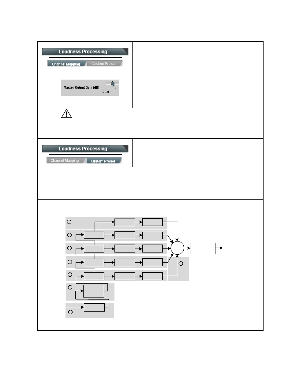
• Master Output Gain Control
Allows fine adjustment of the overall output gain.
(-20.0 dB to 11 dB range in 0.1 dB steps; default = 0.0 dB)
Note: This control is primarily useful in matching the output level to an
alternate LKFS target level if required. Also, it is useful (where
desired) in matching various Processing Profile presets to have
similar output levels. The loudness processor has a default target
loudness of -24 LKFS.
Note:
(USA) ATSC A/85 and the CALM Act (H.R. 1084/S. 2847) requires that when real-time loudness processing is
applied using a fixed target loudness of -24 LKFS, downstream AC-3 encoding must correspondingly use a
fixed dialnorm value of -24. The default target loudness (as set by the loudness processor Master Output Gain
Control) is -24 LKFS. When loudness processing is engaged, make certain AC-3 dialnorm is set as
described here.
Provides custom detailed parametric controls for
modifying any of the factory Presets profiles to suit user
preferences.
Note:
• Modification of default presets settings using the Custom Preset page can have a profound effect on program material
technical and aesthetic aspects. Setup should only be performed by authorized personnel, and should be fully
assessed before being used for on-air programming. Refer to Appendix A. “Linear Acoustic® AEROMAX® Detailed
Description” for detailed descriptions of these parametric controls and their interaction.
• Custom settings may result in loudness processing that is no longer compliant with ITU BS.1770 – ATSC A/85.
The Custom Preset page exposes parametric controls correlating to functional blocks as shown below. Refer to A thru H on the
next page for these controls.
Table 3-2
9985 Function Submenu List — continued
Crossover
Input AGC
Σ
Crossover
Crossover
Crossover
B4 AGC
B3 AGC
B2 AGC
B1 AGC
B4 Limiter
B3 Limiter
B2 Limiter
B1 Limiter
B5 AGC
B5 Limiter
L, R, C,
LFE, Ls, Rs
PCM Inputs
(From Audio
Routing/Gain
Control)
Output Limiter/
Master Gain
Control
B1 BP
B2 BP
B3 BP
B4 BP
B5 BP
HP
HP
HP
L, R, C,
LFE, Ls, Rs
PCM Outputs
Input
Parametric
EQ 1 – 3
A
B
C
D
E
F
G
H