Cj gps speedometer cluster - installation, Figure 3: connection guide, Inverter – Speedhut CJ (Jeep) Speedometer Cluster User Manual
Page 3
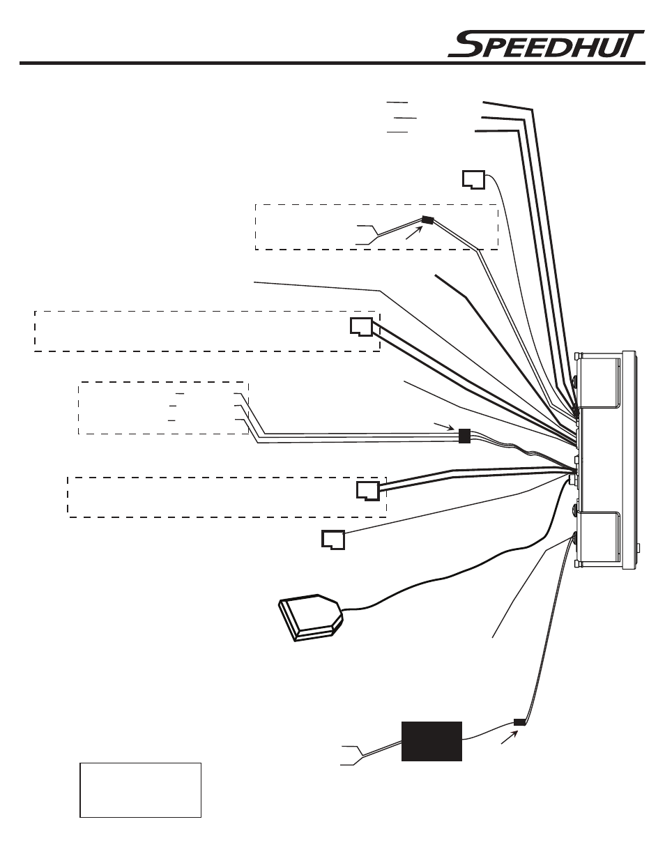
CJ GPS Speedometer Cluster - Installation
Ground (black)
+12 volts Dash lighting (white)
Snap connection
for dial lighting
+12 Volts keyed ignition (
#14
Red)
(
#15
Black)
Ground
(
#13
White)
+12 Volts Dash lighting
Power distribution cable
(
#3
Green/Orange
)
(
#5
Green/Red
)
(
#1
Blue/White )
left turn signal +12V pulse
right turn signal +12V pulse
high beam wire +12V
Inverter
GPS Hot Start (
#8
Red/Black Wire)
Connect to +12VDC non-keyed power.
(25 micro-amp draw) See Figure 8
GPS Antenna
(See
Figure 8)
INVERTER IS REQUIRED FOR GAUGE DIAL LIGHTING
(Pointer (needle) lighting)
(Main gauge power)
(Gauge Dial lighting)
Inverter/Black Box Note: E18-686-5CR is a single gauge inverter to light a single gauge.
C01-18N-2 & C11-18A01 are multiple gauge lighting inverters that can light up to 8 gauges.
***Protect any unused connectors. Damage to an unused connector
could cause inverter failure
.***
Fuel level signal (
#10
Pink)
Tachometer Signal (
#17
Yellow Wire)
(Available on some models)
Attach to included wire harness and connect to Tachometer signal out (See
Figure 9)
Brake Light [GND] (
#7
Black)
Fuel Level Ground Wire (
#9
Yellow/Black)
4X4 Indicator [GND] (
#11
Orange)
Water Temperature Signal (
#12
Yellow/Red)
Water Temperature Ground (
#16
Yellow/Black)
(Wire Pair CAN high
#4
and CAN low
#6
)
OBDII
(See Figure 7 for details)
(Wire Pair
#18
and
#19
)
Snap connection
Note: Tie together the +12VDC
dash lighting wire (#13 white) to
the +12VDC inverter white wire
and connect to the same dash
lighting source.
Snap connection
FIGURE 3: Connection Guide
See Figure #2 for more wiring information and numbering.
Speed signal (
#2
Red/Green)
Attach to included wire harness and connect to Speed Sender (See Figure 4)
- 3 -
Check Engine [GND] (
#20
Purple Wire)
Attach to included wire harness and connect to Fuel Level Sender (See Figure 5)
Attach to included wire harness and connect to Temperature Sender (See Figure 6)